Unregulated DC-DC converter having synchronous rectification with efficient gate drives

a gate drive and synchronous rectification technology, applied in the direction of electric variable regulation, process and machine control, instruments, etc., can solve the problems of reducing the efficiency of the intermediate bus voltage converter, sink current to ground before settling in the off state, etc., to improve the low-load efficiency of the dc-to-dc power converter

Active Publication Date: 2005-06-02
BEL POWER SOLUTIONS INC
View PDF1 Cites 4 Cited by
  • Summary
  • Abstract
  • Description
  • Claims
  • Application Information

AI Technical Summary

Benefits of technology

[0010] In another embodiment of the invention, a method of improving low-load efficiency of the DC-to-DC power converter comprises absorbing charge across the first and second synchronous rectifiers during respective off states of the first and second synchronous rectifiers, and injecting charge into the control terminals of the first and second synchronous rectifiers during r

Problems solved by technology

With the increasing complexity of electronic systems, it is common for an electronic system to require power provided at several different discrete voltage and current levels.
Since it is undesirable to deliver relatively high current at low voltages over a relatively long distance through an electronic device, it is known to distribute an intermediate bus voltage throughout the electronic system, and include an individual point-of-load (“POL”) regulator, i.e., DC/DC

Method used


Image

  • Unregulated DC-DC converter having synchronous rectification with efficient gate drives
  • Unregulated DC-DC converter having synchronous rectification with efficient gate drives
  • Unregulated DC-DC converter having synchronous rectification with efficient gate drives

Examples


Embodiment Construction

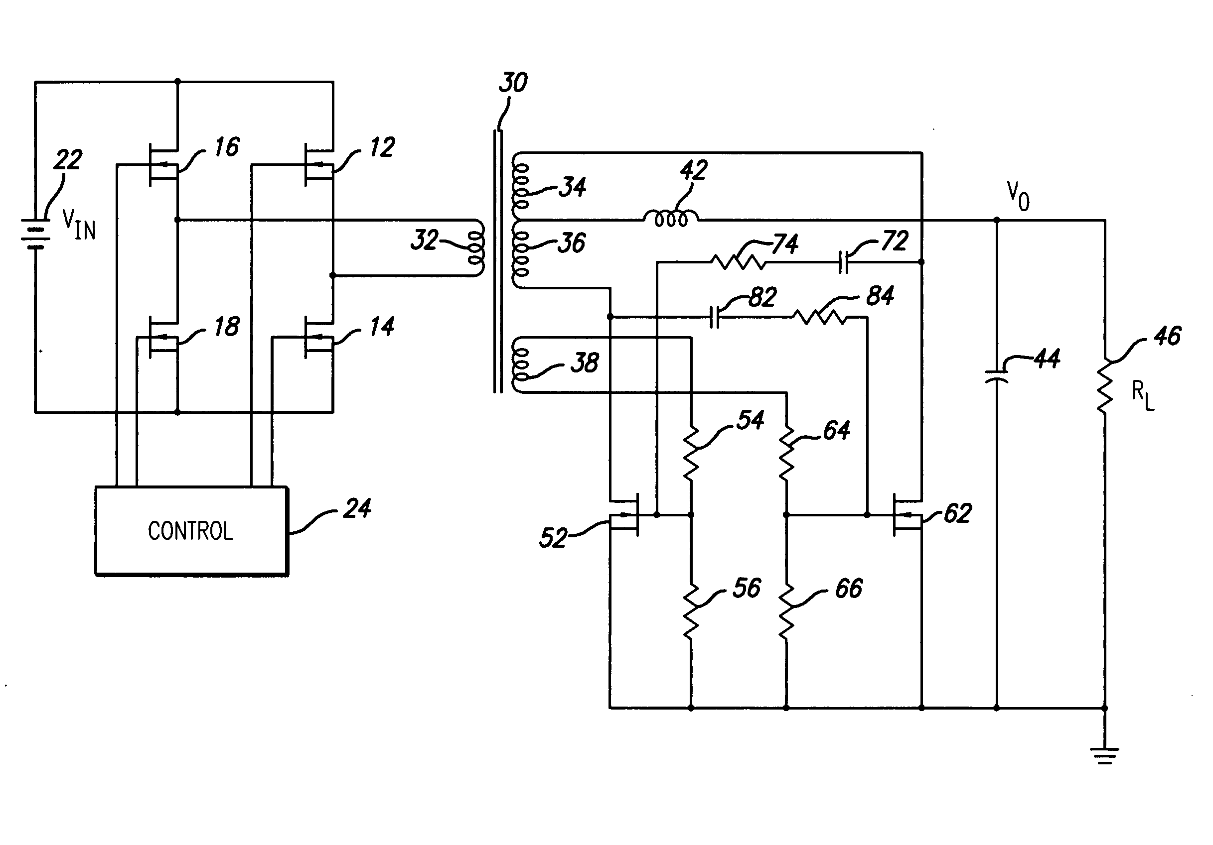
[0017] The present invention provides an unregulated DC-to-DC power converter suitable for intermediate bus voltage converter applications in which the synchronous rectifiers are driven efficiently to provide faster transition time and reduced loss. In the detailed description that follows, like element numerals are used to describe like elements illustrated in one or more figures.

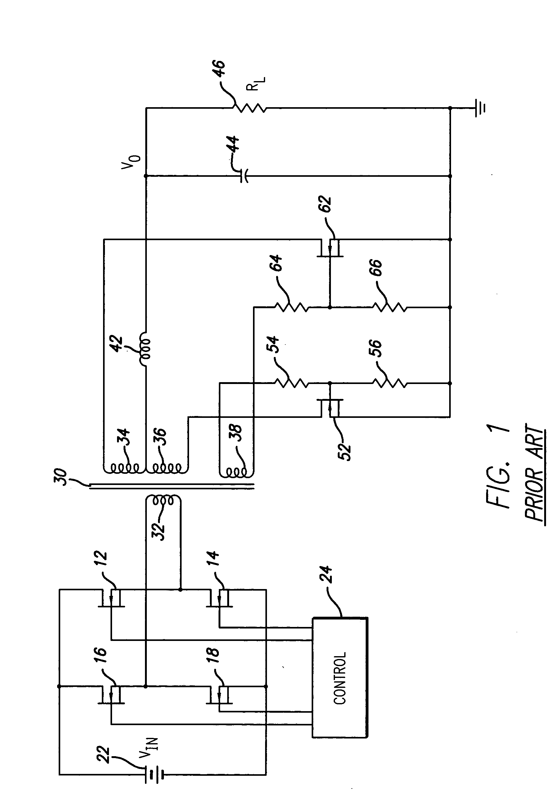
[0018] Referring first to FIG. 1, a prior art DC-to-DC power converter is shown. The power converter of FIG. 1 provides a DC output voltage (VO) that is isolated from the input voltage (VIN), and includes a transformer 30 having a primary winding 32 and a plurality of secondary windings 34, 38. On the primary side of the transformer is a conventional full bridge topology, two pairs of primary power switches 12, 14 and 16, 18 provide alternating current to the primary winding 32. In particular, the first pair of power switches 12, 14 are arranged in series with the input voltage (VIN), with a junction betw...


PUM


Abstract

An unregulated DC-to-DC power converter suitable for intermediate bus voltage converter applications includes synchronous rectifiers that are driven efficiently to provide faster transition time and reduced loss. The DC-to-DC power converter comprises a transformer having a primary winding and at least first and second secondary windings. An input circuit is coupled to the primary winding and is adapted to apply an alternating polarity square wave voltage to the primary winding. An output circuit comprising an output filter is coupled to a tap of the first secondary winding. The output filter provides a DC output voltage. A first synchronous rectifier is coupled to a first end of the first secondary winding and a second synchronous rectifier is coupled to a second end of the first secondary winding. The second secondary winding has a first end coupled to a control terminal of the first synchronous rectifier and a second end coupled to a control terminal of the second synchronous rectifier. A first snubber circuit is coupled between the control terminal of the first synchronous rectifier and the second end of the first secondary winding. A second snubber circuit is coupled between the control terminal of the second synchronous rectifier and the first end of the first secondary winding. The first and second snubber circuits provide faster transition of the first and second synchronous rectifiers, respectively, between on and off states.

Description

BACKGROUND OF THE INVENTION [0001] 1. Field of the Invention [0002] The present invention relates to power converter circuits, and more particularly, to an unregulated DC-to-DC power converter suitable for intermediate bus applications in which synchronous rectifiers are efficiently driven to provide faster transition time and reduced loss. [0003] 2. Description of Related Art [0004] With the increasing complexity of electronic systems, it is common for an electronic system to require power provided at several different discrete voltage and current levels. For example, electronic systems may include discrete circuits that require voltages such as 3v, 5v, 9v, etc. Further, many of these circuits require a relatively low voltage (e.g., 1v), but with relatively high current (e.g., 100 A). Since it is undesirable to deliver relatively high current at low voltages over a relatively long distance through an electronic device, it is known to distribute an intermediate bus voltage throughou...

Claims


Application Information

Patent Timeline
IPC IPC(8): H02M3/335H02M7/5387
CPCH02M1/34Y02B70/1475H02M2001/348H02M3/33592H02M1/348Y02B70/10H02M3/24H02M3/28H02M3/325
Inventor CARON, DONALD RICHARD
Owner BEL POWER SOLUTIONS INC
Why Eureka
Try Eureka