Honeycomb forming ferrule and jig for honeycomb forming ferrule using the ferrule

a technology of honeycomb and ferrule, which is applied in the direction of dough shaping, manufacturing tools, food shaping, etc., can solve the problems of large wear, unstable structure of extruded honeycomb, and large wear of the body, and achieve high toughness

Inactive Publication Date: 2005-06-02
NGK INSULATORS LTD
View PDF14 Cites 24 Cited by
  • Summary
  • Abstract
  • Description
  • Claims
  • Application Information

AI Technical Summary

Benefits of technology

[0011] In the present invention, it is preferable that the cemented carbide is formed by compacting, followed by sintering at h

Problems solved by technology

However, when a honeycomb structure containing SiC and the like is manufactured using the die, the die is greatly worn by a passing resistance which is caused when SiC contained in a raw material flows in the die.
Accordingly, when kneaded clay

Method used


Image

  • Honeycomb forming ferrule and jig for honeycomb forming ferrule using the ferrule
  • Honeycomb forming ferrule and jig for honeycomb forming ferrule using the ferrule
  • Honeycomb forming ferrule and jig for honeycomb forming ferrule using the ferrule

Examples


example 1

Comparative Examples 1 and 2

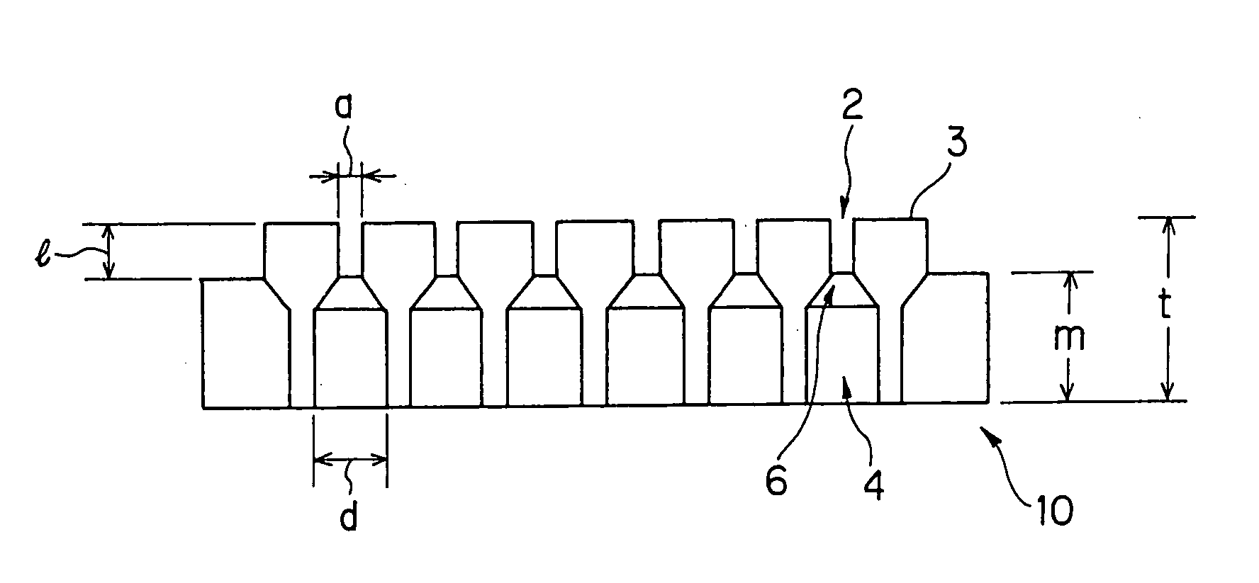
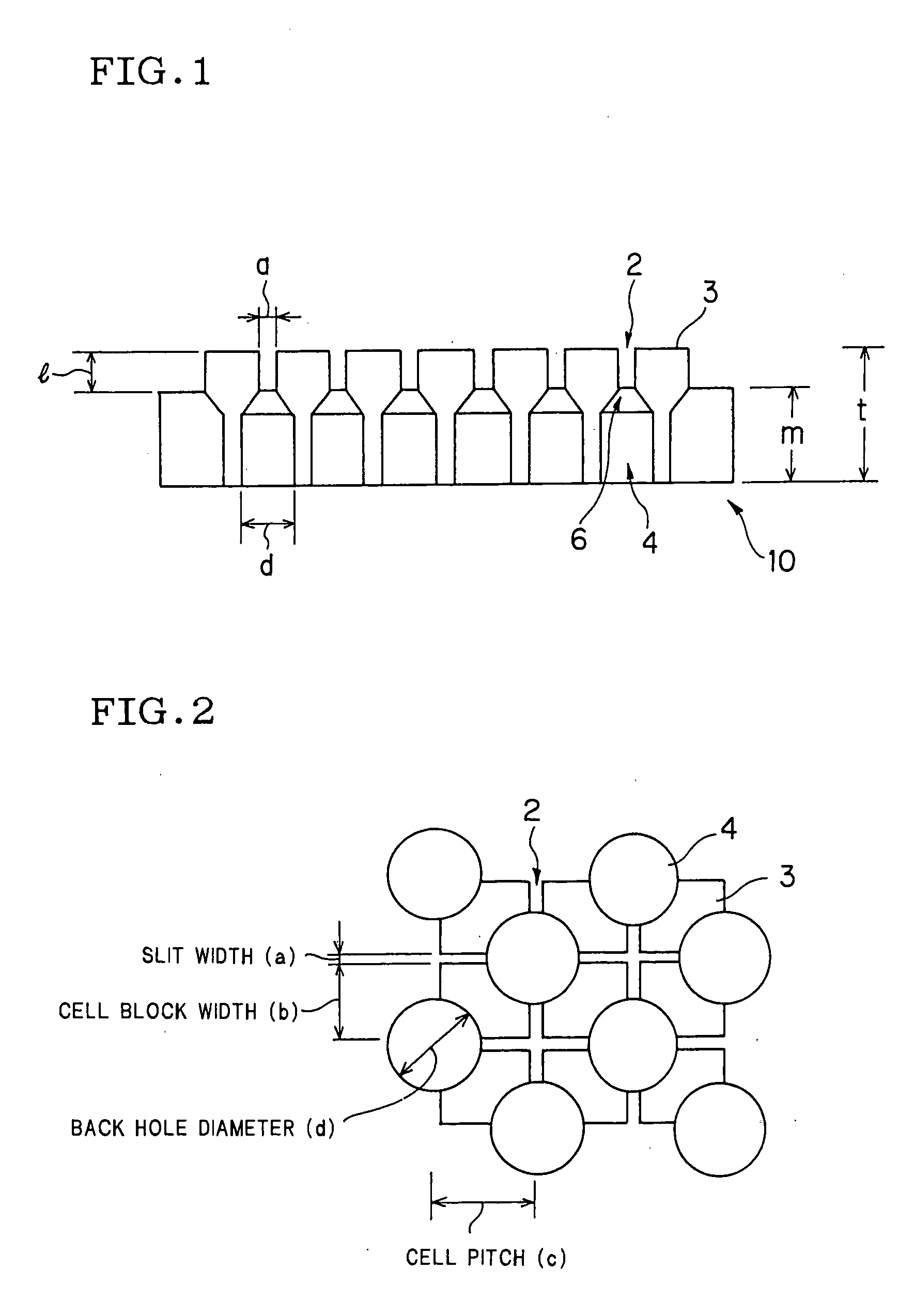
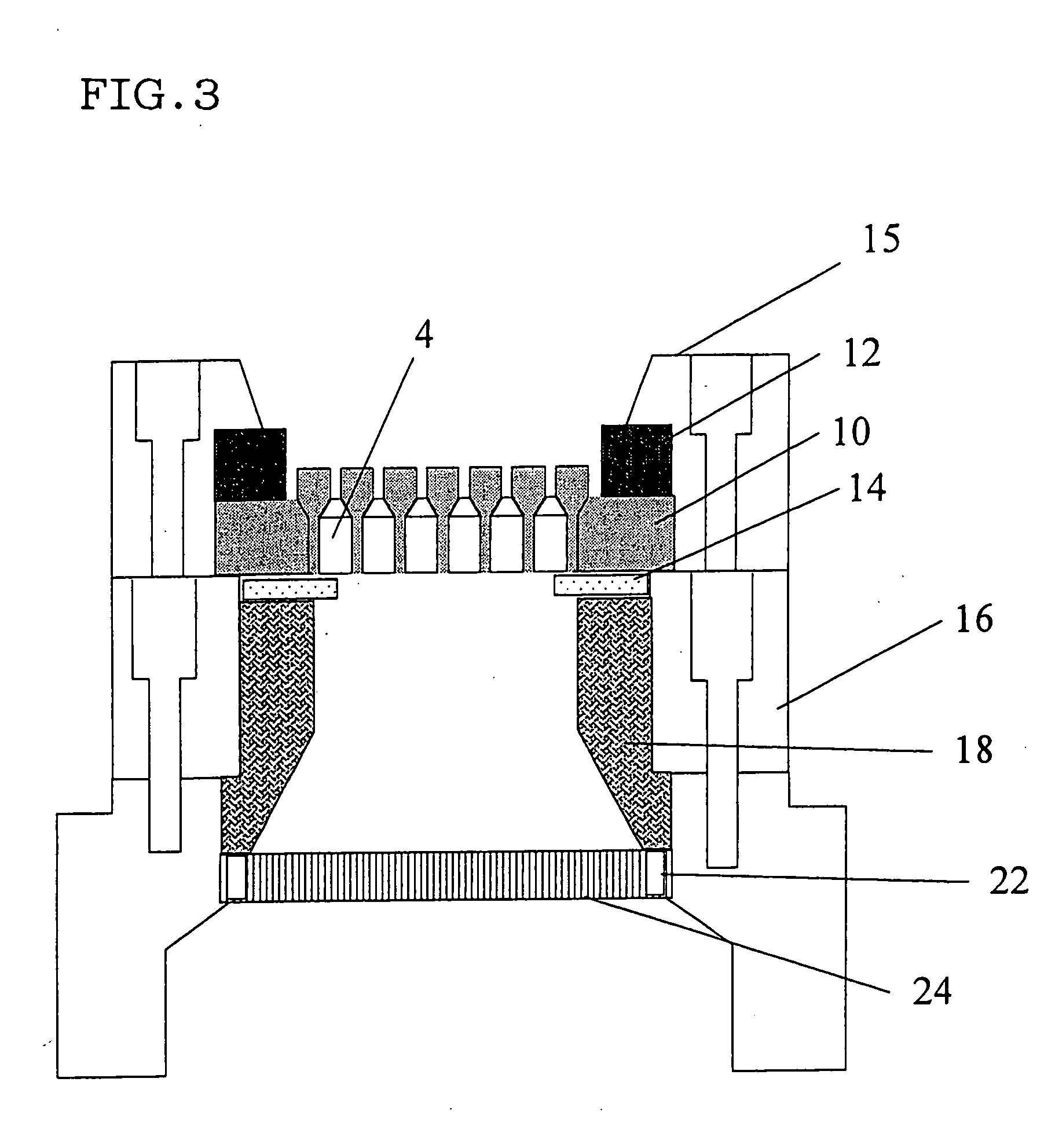
[0038] Honeycomb structures were extruded, respectively using a cemented carbide die shown in Table 1 (embodiment 1; a connection area ratio of back holes and cell blocks was 50% (refer to FIG. 2) and the cell blocks had the height (1) of 3 mm) and surface-treated stainless steel dies (comparative examples 1 to 2) shown in Table 1. The results are shown in Table 1.

TABLE 1Dispersion ofType of dieWear resistanceconfiguration sBase materialSurface treatment(*1)(*2)Embodiment 1Cemented carbideAbsent1000.02(WC-Co)ComparativeStainless steelNon electrolytic 1  0.80example 1material (C-450)plating treatmentthickness: 50 μmComparativeCVD film thickness: 5  0.50example 215 μm

(*1) Wear resistance: when wear resistance of the comparative example was set to 1.

(*2) Dispersion of configuration: a standard deviation of 100 diagonal line cross points was calculated.

[0039] From the results of Table 1, wear resistance of the cemented carbide die (embodiment 1) is at le...

examples 2 to 4

Comparative Examples 3 and 4

[0040] Honeycomb bodies were extruded, respectively using cemented carbide dies (embodiments 2 to 4 and comparative example 3 to 4, in which cell blocks had a height (1) of 3 mm) in which a connection area ratio of cell blocks and back holes was set as shown in Table 2. The results are shown in Table 2.

TABLE 2Connection arearatio of cellblock - kneadedPresence / absenceExtrusion ofclay introductionof broken cellDispersion ofhoneycombhole (%)blockconfiguration (s) *2structureEmbodiment 235Absent0.30◯Embodiment 350Absent0.02◯Embodiment 465Absent0.20◯Comparative30Present0.50Δexample 3Comparative70Present—Xexample 4

*2 Dispersion of configuration: a standard deviation of 100 diagonal line cross points was calculated.

[0041] From the results of Table 2, the honeycomb structures could be excellently extruded without breakage of the cell blocks in the dies in extrusion and with a less amount of change of configuration by setting the connection area ratio of the ...

examples 5 to 7

Comparative Examples 5 and 6

[0044] Honeycomb bodies were extruded, respectively using cemented carbide dies (embodiments 5 to 7 and comparative examples 5 to 6) made such that a connection area ratio of cell blocks and back holes was set to 50% (refer to Table 2) and that the cell blocks had a height (1) as shown in Table 3, respectively. The results are shown in Table 3.

TABLE 3OutsideHeightPresence / appearance ofof cellabsenceproductExtrusion ofblockof broken(presence / absencehoneycomb(mm)cell blockof crack)structureEmbodiment 52AbsentAbsent◯Embodiment 63AbsentAbsent◯Embodiment 75AbsentAbsent◯Comparative1AbsentPresentXexample 5Comparative7PresentAbsentXexample 6

[0045] From the results of Table 3, extruded honeycomb structures and products molded after the honeycomb structures were extrude had an excellent outside appearance in the embodiments 5 to 7 because the cell blocks of the dies were not broken in extrusion by setting a height of the cell blocks to 2 to 5 mm.

[0046] Note tha...


PUM

PropertyMeasurementUnit
Fractionaaaaaaaaaa
Heightaaaaaaaaaa
Fractionaaaaaaaaaa

Abstract

There is disclosed a die (10) for forming a honeycomb body having a structure provided with groovy slits (2) on a front face thereof, the slits being formed by cell blocks (3) and back holes (4) on a back surface thereof, each hole being communicatively connected with the slit. The die (10) is made of cemented carbide having wear resistance. The cemented carbide is formed by compacting, followed by sintering at high temperature, metal carbide powder of transition metal element series with an iron group metal binder having toughness. A connection area ratio of the back hole (4) and the cell block (3) is 35 to 65%. According to the die for forming a honeycomb body and the die jig for forming a honeycomb body using the same, wear resistance of the die or the die jig can be enhanced when the raw material containing the material having very high hardness such as SiC and the like is extruded as well as the defect in shape of an extruded body due to wear of the die can be overcome.

Description

TECHNICAL FIELD [0001] The present invention relates to a die for forming a honeycomb body and a jig for forming a honeycomb body using the die. BACKGROUND ART [0002] A honeycomb structure has been used in a filter for trapping particulate matter in exhaust gas from an internal combustion engine, boiler, and the like, particularly diesel particulate matter. [0003] Heretofore, as a die for extruding a ceramic honeycomb body, there has been known the die (10) for extruding a honeycomb body, which is provided with groovy slits on the front face of a base metal made of stainless steel and iron, the groovy slits being formed by cell blocks, and provided with back holes, on a back face thereof, each communicatively connected with the slit. [0004] In the die for forming a honeycomb body arranged as described above, after, for example, a nickel plated layer is formed on a front face of a cell block body, a surface treatment is conducted to form a CVD or PVD layer, which is composed of at le...

Claims


Application Information

Patent Timeline
IPC IPC(8): B28B3/20B28B3/26B29C48/11B29C48/30B29C48/32
CPCB23H9/00B23H2200/30B28B3/26B29L2031/60B29C47/0028B29C47/0852B29C47/12B28B3/269B29C48/11B29C48/3003
Inventor KANEKO, TAKAHISANATE, MASAYUKIHIRONAGA, MASAYUKIDEGUCHI, YUJI
Owner NGK INSULATORS LTD
Why Eureka
Try Eureka