Integrated circuit having a mixer circuit

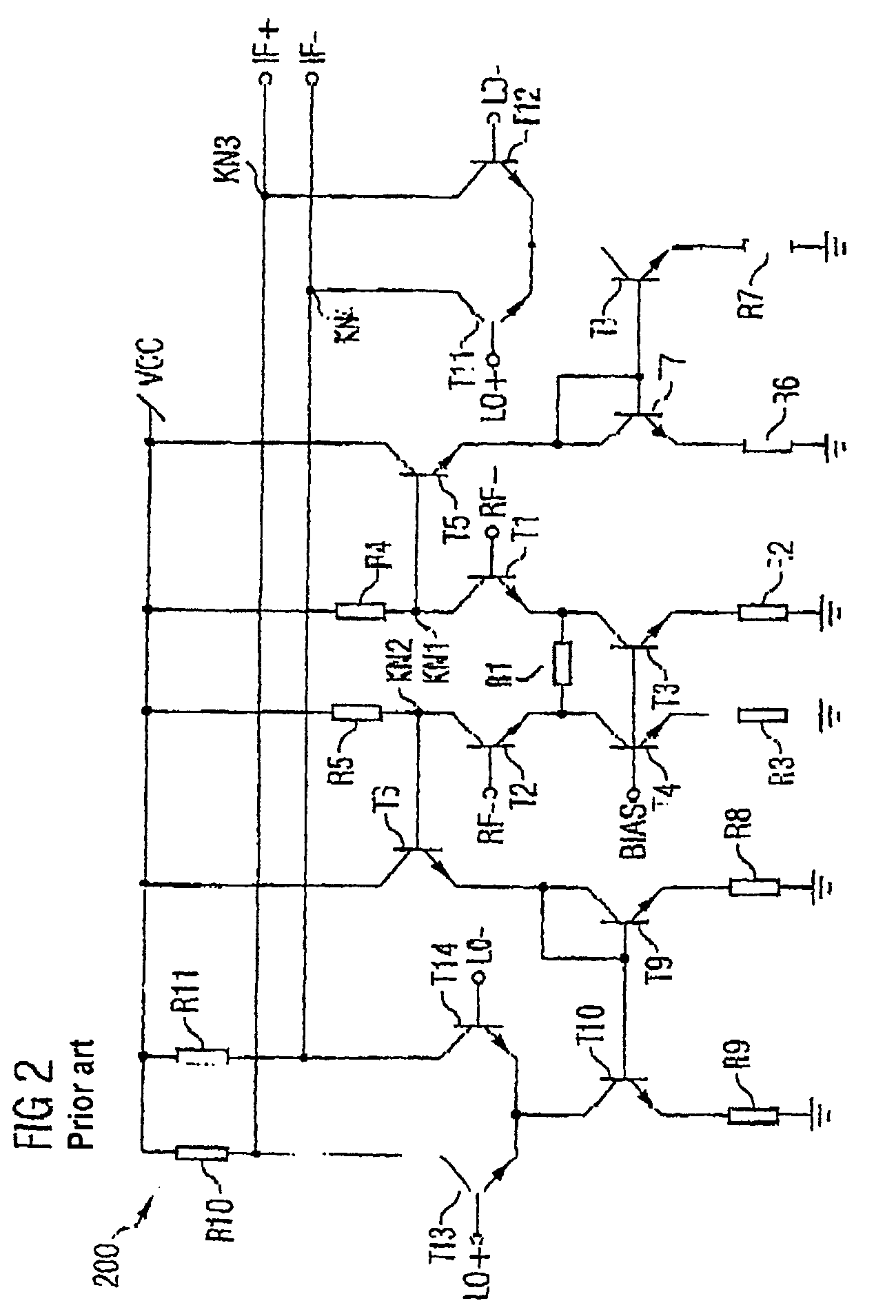
a mixer circuit and integrated circuit technology, applied in the field of integrated circuits, can solve the problems of limited number of transistors, limited operating voltage of transistors, and slow current mirrors within the “current-folded” mixer circuit b>200/b>, so as to reduce parasitic capacitance and reduce operating voltage in individual circuit sections

Active Publication Date: 2005-06-02
INTEL CORP
View PDF17 Cites 26 Cited by
  • Summary
  • Abstract
  • Description
  • Claims
  • Application Information

AI Technical Summary

Benefits of technology

[0023] The integrated circuit preferably has an amplifier circuit between the two radiofrequency terminals and the transformer. This has the advantage that the operating voltages in the individual circuit sections can be reduced further.
[0024] The integrated circuit preferably has at least one filter element. The filter element, for its part, preferably has a cascode. A cascode reduces parasitic capacitances and thus affords the advantage that even relatively high frequencies can be processed in the integrated circuit and not be unintentionally filtered out. In addition or as an alternative, the filter element may have a bandpass filter. The bandpass filter is preferably realized by means of at least one capacitor.

Problems solved by technology

Consequently, the breakdown voltage of the transistors limits the permissible magnitude of the operating voltage applied across all the transistors.
This furthermore has the consequence that the number of transistors is limited in the design of an integrated circuit having a plurality of transistors connected in series.
However, the “current-folded” mixer circuit 200 has the disadvantage that the current mirrors within the “current-folded” mixer circuit 200 are generally slow.
Since this is undesirable, the “current-folded” mixer circuit 200 can only be operated with low operating frequencies if reliable signal conversion and signal transmission are to be effected.

Method used


Image

  • Integrated circuit having a mixer circuit
  • Integrated circuit having a mixer circuit
  • Integrated circuit having a mixer circuit

Examples


Embodiment Construction

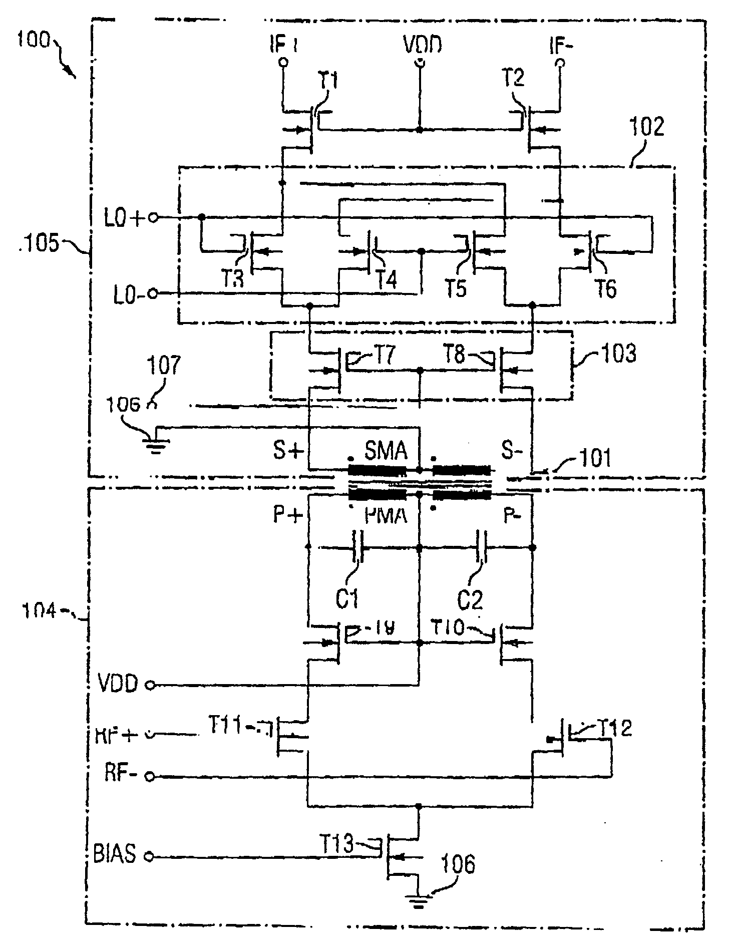
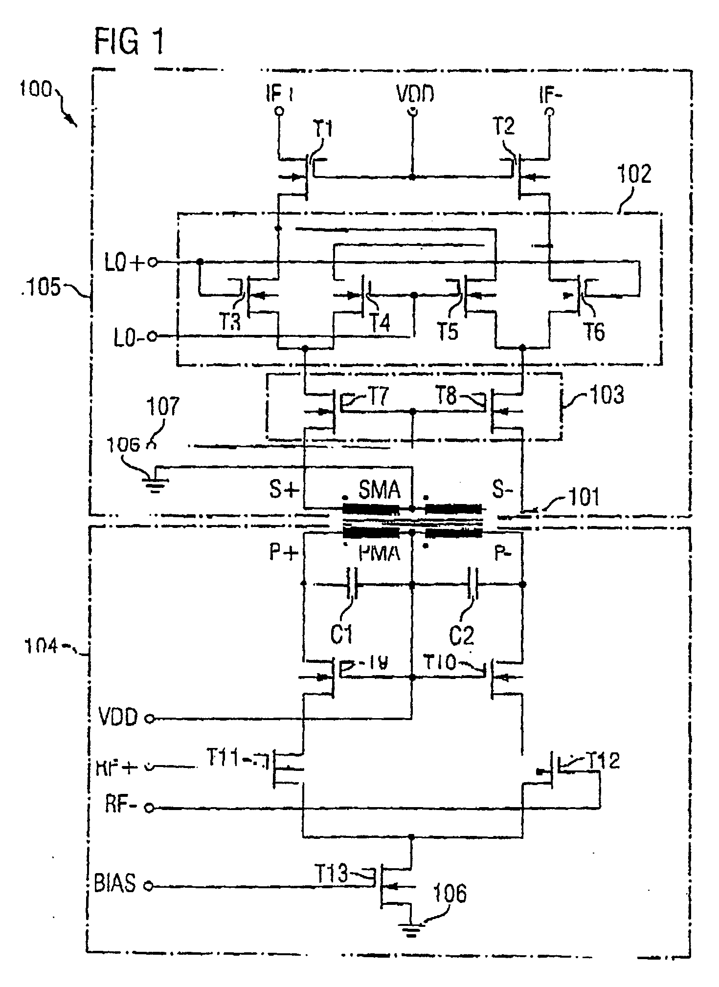
[0036]FIG. 1 shows an integrated circuit 100 in accordance with a first exemplary embodiment of the invention.

[0037] The integrated circuit 100 in accordance with the first exemplary embodiment of the invention has a mixer circuit and a transformer 101. The mixer circuit, for its part, has an active mixer unit 102 with a signal-amplifying unit 103, two reference oscillator terminals LO+, LO−, two radiofrequency terminals RF+, RF− and two intermediate frequency terminals IF+, IF−. In this case, the integrated circuit 100 is set up in such a way that the transformer 101 decouples the two radiofrequency terminals RF+, RF− from the active mixer unit 102.

[0038] The transformer 101 thus clearly has the function of an isolating transformer. In accordance with the exemplary embodiment, all the active components of the integrated circuit 100 are realized by means of field effect transistors (=FET) in 120 nm CMOS technology. Moreover, the mixer circuit of the integrated circuit 100 is const...


PUM


Abstract

Integrated circuit including a mixer circuit, which has a first circuit section, a second circuit section, and a transformer. The first circuit section has two radiofrequency terminals. The second circuit section has two reference oscillator terminals, an active mixer unit with a signal-amplifying unit, and two intermediate frequency terminals. The active mixer unit and the signal-amplifying unit have a common current path. The transformer directly electrically decouples the two radiofrequency terminals from the active mixer unit, and couples the first circuit section and the second circuit section together such that each of the two circuit sections is separately supplied with a full operating voltage of the integrated circuit. The integrated circuit may additionally include a second transformer connected between the active mixer unit and the two intermediate frequency terminals.

Description

CROSS-REFERENCE TO RELATED APPLICATION [0001] This application is a continuation of International Patent Application Serial No. PCT / DE03 / 01204, filed Apr. 10, 2003, which published in German on Nov. 13, 2003 as WO 03 / 094339, and is incorporated herein by reference in its entirety. FIELD OF THE INVENTION [0002] The invention relates to an integrated circuit, and in particular to an integrated circuit having a mixer circuit. BACKGROUND OF THE INVENTION [0003] A mixer circuit serves as a downconverter for the frequency conversion of a radiofrequency signal (radiofrequency=RF) into an intermediate frequency signal (intermediate frequency=IF) or as an upconverter in the opposite direction, a local oscillator signal (LO) being used for the frequency conversion. In this case, the frequency fIF of the intermediate frequency signal results from the frequency fRF of the radiofrequency signal and the frequency fLO of the local oscillator signal in accordance with fIF=fRF±fLO. An elementary mul...

Claims


Application Information

Patent Timeline
Patent Type & Authority Applications(United States)
IPC IPC(8): H03D7/14
CPCH03D7/1441H03D7/1433H03D2200/0084H03D2200/0033H03D7/1458
Inventor LANGENBERG, JORGLIEBERMANN, THOMASSIMBURGER, WERNERTIEBOUT, MARCWOHLMUTH, HANS-DIETER
Owner INTEL CORP
Why Eureka
Try Eureka