Device for monitoring penetration into anatomical members

a technology for penetrating devices and anatomical structures, applied in the field of material penetration, can solve the problems of frequent occurrence, expensive and cumbersome implementation, and piercing of vertebral bone cortex, and achieve the effect of preventing any lesion

Inactive Publication Date: 2005-06-02
SPINEGUARD A FRENCH SAS +1
View PDF36 Cites 155 Cited by
  • Summary
  • Abstract
  • Description
  • Claims
  • Application Information

AI Technical Summary

Benefits of technology

[0023] The present invention aims to remedy the drawbacks of the prior art by proposing a device that allows real-time monitoring of the penetration of the penetrating means (the drilling means or the like) into the material, by measuring the differences in a physical quantity as the penetration proceeds, so as to allow the user to know where the end of the penetrating means is and thus prevent any lesion.

Problems solved by technology

In spinal surgery, for example, when drilling the pedicle, it frequently happens that the vertebral bone cortex is pierced, broken or chipped by the penetrating drill bit.
Surgeons sometimes use equipment such as the following: equipment for surgical navigation, which is expensive and cumbersome to implement; equipment for monitoring of sensory and / or motor evoked potentials, this being less expensive but also restricting as it requires the presence of a specialist whose mission is solely to carry out this monitoring operation.
As a result, in most cases the operators rely solely on their knowledge of anatomy and their experience in order to accomplish this risky surgical procedure.
Furthermore, that system requires, for each patient, an experimental determination of the impedance values or of the changes in impedance, as explained on the last page of that application, which absolutely does not allow this system to be adapted for the purpose of preventing a determined depth being reached.
That instrument allows the user to be informed, after having made a cavity, about the depth of this cavity; it does not allow real-time monitoring of the penetration of a penetrating means into anatomical structures.
Another drawback of the techniques of the prior art is that are cumbersome to implement and tend to extend the operation time, thus increasing the associated risks.

Method used


Image

  • Device for monitoring penetration into anatomical members
  • Device for monitoring penetration into anatomical members
  • Device for monitoring penetration into anatomical members

Examples


first embodiment

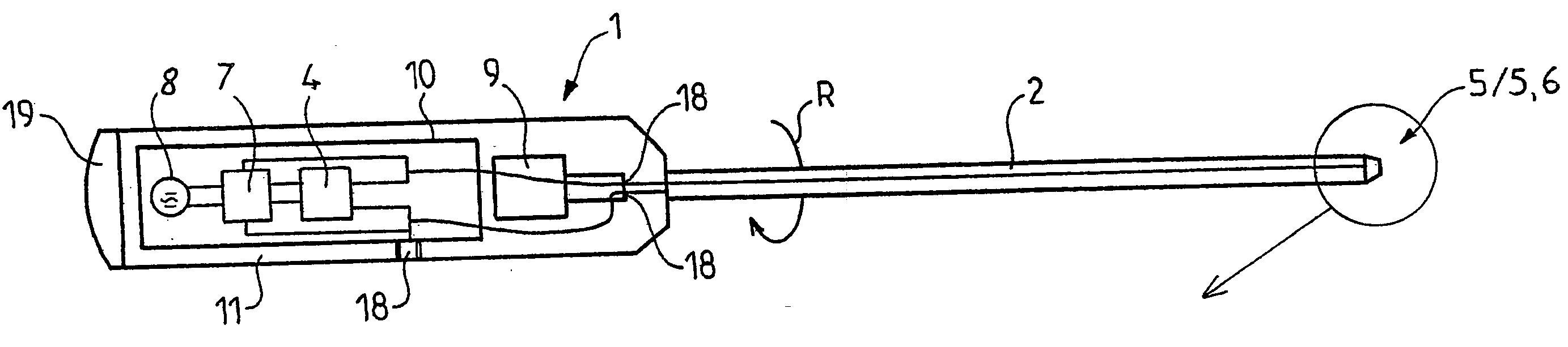
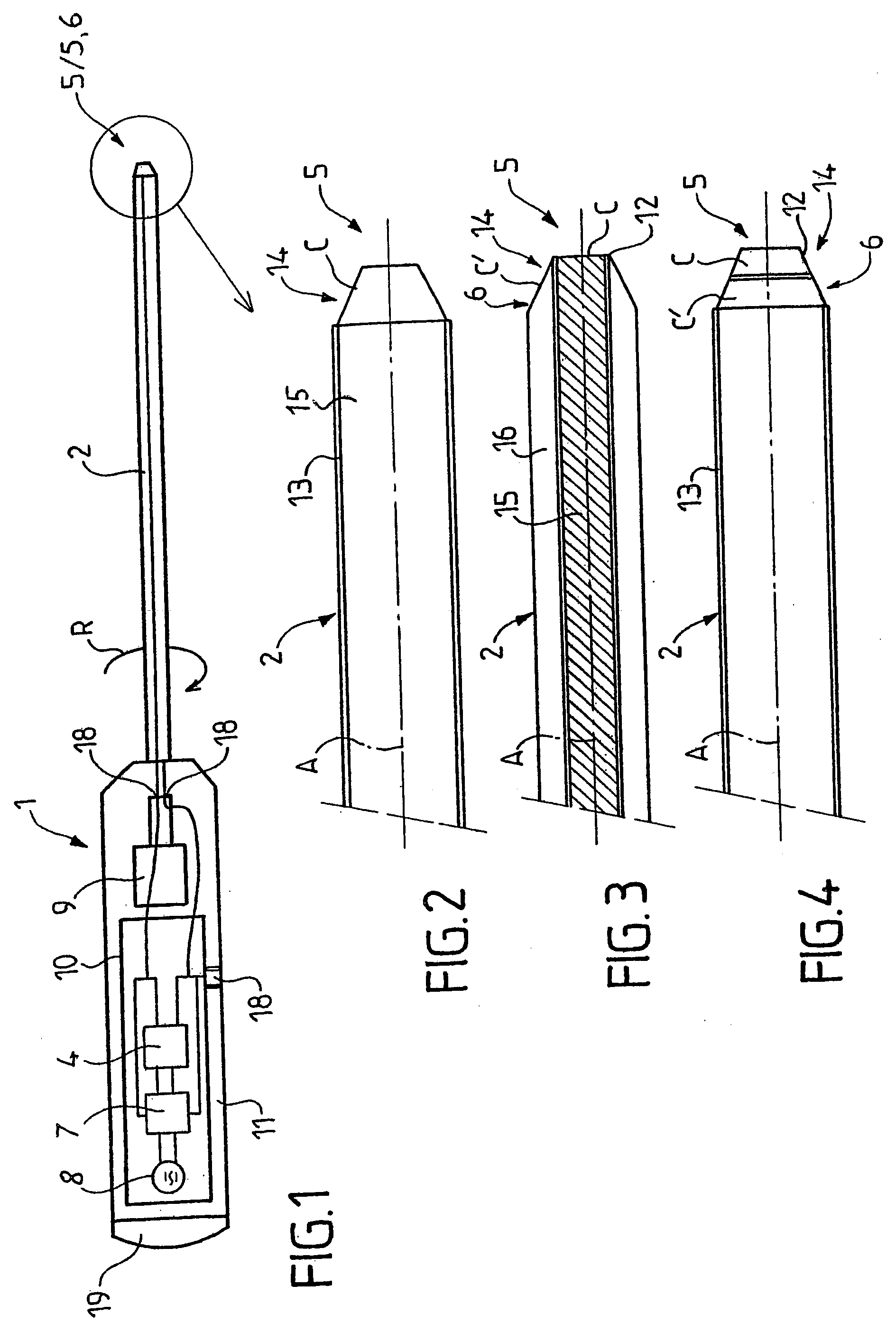
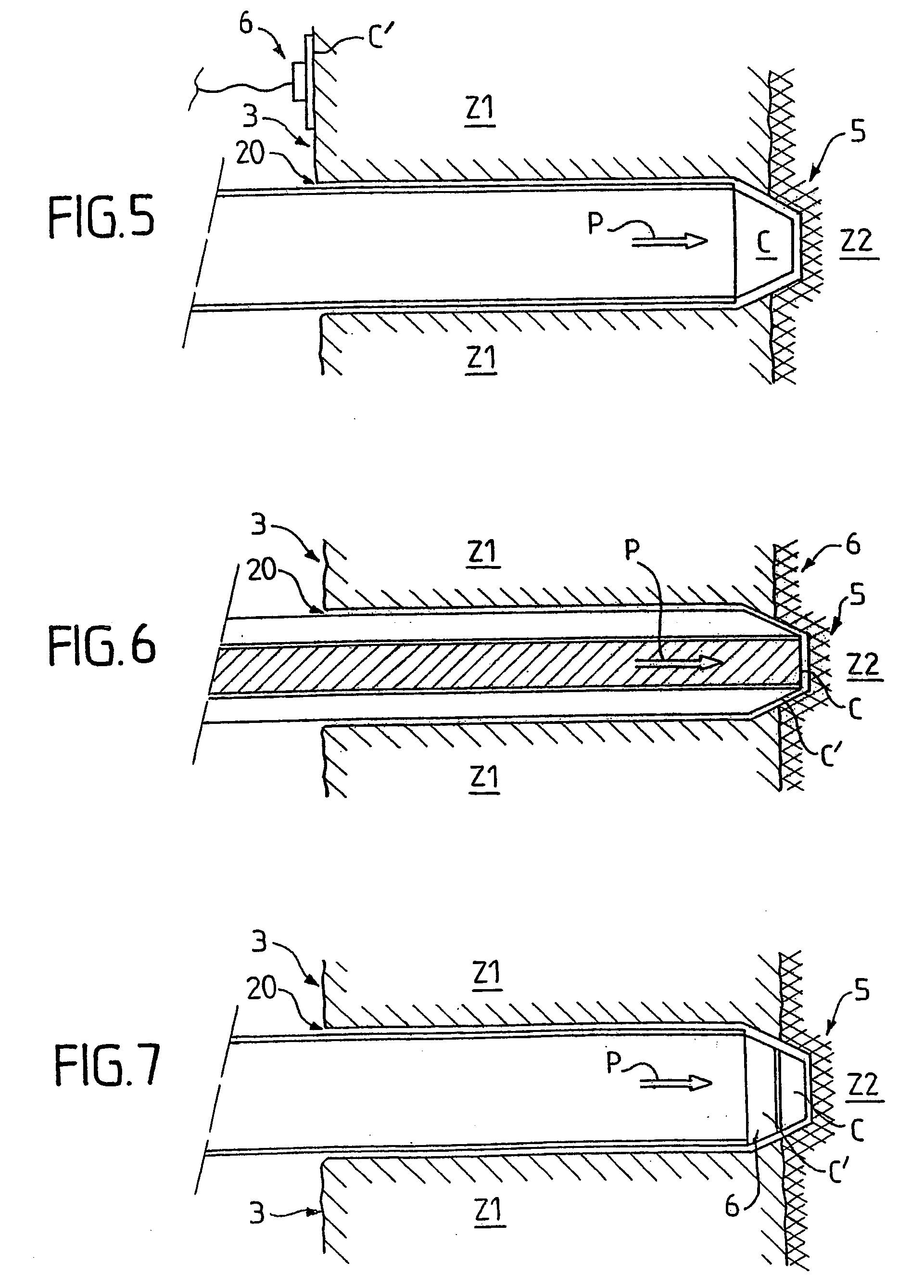
[0098] In a first embodiment, illustrated in FIGS. 2 and 5, a distal electrode (5) is formed by a contact surface C located at the distal end of said penetrating means (2) and another, proximal electrode (6) is formed by a contact surface C′ intended to be positioned on an outer surface of the anatomical structures, including on the operation incision.

[0099] The penetrating means (2) has a central portion (15) that is conducting and a peripheral portion (13) that is insulated right to a distal end (14) bared, that is to say not insulated, over a few millimeters. The surface C has an area of less than 10 mm2, around 4 mm2, and the surface C′ has an area of around 20 mm2.

[0100] Thus, the first pole of the electronic stimulation / measurement device is formed by the distal end of the penetrating means (2) of the instrument and the other pole is formed by a reference connection on the patient.

second embodiment

[0101] In a second embodiment, illustrated in FIGS. 3 and 6 on the one hand and 4 and 7 on the other, said electrodes (5, 6) are each formed by a contact surface C, C′ respectively, which is located at the distal end of said penetrating means (2), said contact surfaces C, C′ being separated by an insulator (12).

[0102] In the version illustrated in FIGS. 3 and 6, the penetrating means (2) comprises a conducting central portion (15) and a conducting outer portion (16), said central portion (15) and said outer portion (16) being separated by a cylindrical insulator (12). The two conducting portions each form one pole of the electronic device.

[0103] Thus, the outer portion (16) forms a conducting outer tube, hollow at its center, and the central portion (15) forms a conducting inner cylinder, the central (15) and outer (16) portions both emerging at the end of the penetrating means (2) so as to form the two surfaces C and C′ that are isolated from each other.

[0104] In this version, th...


PUM


Abstract

The invention relates to a device that can be used to monitor the penetration of a penetration member into anatomical structures and, in particular, bone structures of a living body, the structures having at least two different electrical impedance areas. The device is characterized in that it comprises: at least one impedance meter which can be connected to at least two electrodes, at least one of the electrodes being located at a distal end of the penetration member; and at least one alert device which can produce an alert signal if the impedance meter detects an impedance variation. The invention also relates to a penetration member for the device and to an electronic board for the device.

Description

BACKGROUND OF THE INVENTION [0001] (1) Field of the Invention [0002] The present invention relates to the field of the penetration of material, such as bone structures or the like, that exhibit differences in intrinsic physical quantities. [0003] The present invention relates more particularly to a device for monitoring the penetration of a penetrating means into anatomical structures, and especially bone structures, of a living body, said structures having at least two regions of different electrical impedance. [0004] (2) Prior Art [0005] In spinal surgery, for example, when drilling the pedicle, it frequently happens that the vertebral bone cortex is pierced, broken or chipped by the penetrating drill bit. Depending on the authors, 15 to 40% of pedicle screws are thus improperly positioned, with a clinical manifestation (pain, paralysis, hemorrhaging, etc.) in 1 to 2% of the cases and therefore require further intervention. [0006] Surgeons sometimes use equipment such as the follo...

Claims


Application Information

Patent Timeline
Patent Type & Authority Applications(United States)
IPC IPC(8): A61B5/05A61B5/053A61B5/103A61B17/16A61B17/56A61B19/00A61N1/36
CPCA61B5/053A61B5/0538A61B5/417A61B5/4504A61N1/36014A61B17/1626A61B17/1671A61B2019/481A61B17/1615A61B2090/062A61B2090/08021A61B1/317
Inventor BOURLION, MAURICEVANQUAETHEM, ALAIN
Owner SPINEGUARD A FRENCH SAS
Why Eureka
Try Eureka