Rapid thermal processing system, method for manufacuturing the same, and method for adjusting temperature

a thermal processing system and thermal processing technology, applied in the direction of coatings, chemical vapor deposition coatings, metallic material coating processes, etc., can solve the problems of optical pyrometers not being able to measure the exact temperature of the substrate, the substrate is cracked, and the production yield is significantly reduced, so as to improve the temperature controllability around the substrate edge, suppress the effect of the change in the emissivity of the substrate carrier during the processing

Inactive Publication Date: 2005-06-09
PANASONIC CORP
View PDF3 Cites 6 Cited by
  • Summary
  • Abstract
  • Description
  • Claims
  • Application Information

AI Technical Summary

Benefits of technology

[0037] To be more specific, with the present invention, since a substrate carrier of the rapid thermal processing system has oxidation resistance, it becomes difficult to oxidize or oxynitride the substrate carrier even if the processing is carried out either at a relatively high temperature or in an atmosphere having a relatively strong ability of oxidization or oxynitriding. Therefore, a change in the emissivity of the substrate carrier during the processing can be suppressed. This accurately transfers the temperature around the edge of a substrate to a temperature control system including a thermal processing mechanism. As a result, the temperature controllability around the substrate edge can be improved to suppress slips or the like in the substrate, which dramatically boosts yields of devices to be processed.
[0038] Moreover, in the present invention, the quantity of temperature dependence is acquired by carrying out rapid thermal processing on the substrate, and then temperature shifts of individual optical pyrometers are independently corrected based on the acquired quantity of temperature dependence. Therefore, the measurement temperatures of the optical pyrometers can be corrected so that the quantity of temperature dependence has a value corresponding to a desired temperature, so that the temperature shifts within the substrate surface caused by the rapid thermal processing can be made uniform with high precision. Accordingly, the temperature controllability can be improved even around the substrate edge to suppress slips or the like in the substrate, which dramatically boosts yields of devices to be processed.

Problems solved by technology

In some instance, this may bring about cracking of the substrate or other troubles, and eventually production yields are significantly reduced.
As a result of this, the optical pyrometer cannot measure the exact temperature of the substrate, and an inexact measurement temperature thereof is transferred to the thermal processing mechanism.
However, as described above, in the case where an accurate temperature measurement cannot be performed due to the influences of the substrate carrier, the highly precise temperature control of the substrate edge is extremely difficult to carry out.

Method used


Image

  • Rapid thermal processing system, method for manufacuturing the same, and method for adjusting temperature
  • Rapid thermal processing system, method for manufacuturing the same, and method for adjusting temperature
  • Rapid thermal processing system, method for manufacuturing the same, and method for adjusting temperature

Examples


first embodiment

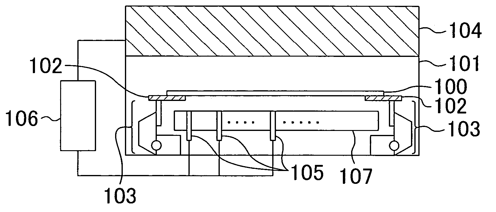
[0062] A rapid thermal processing system according to a first embodiment of the present invention will be described below with reference to the accompanying drawings.

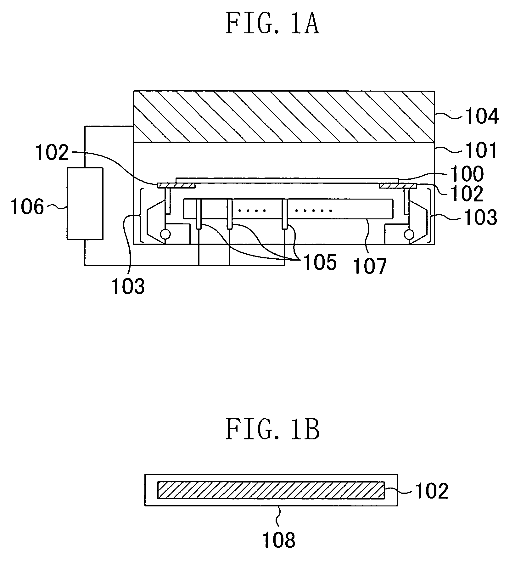
[0063]FIG. 1A is a view showing a schematic structure of the rapid thermal processing system according to the first embodiment, and FIG. 1B is a view showing a sectional structure of a substrate carrier of the rapid thermal processing system according to the first embodiment.

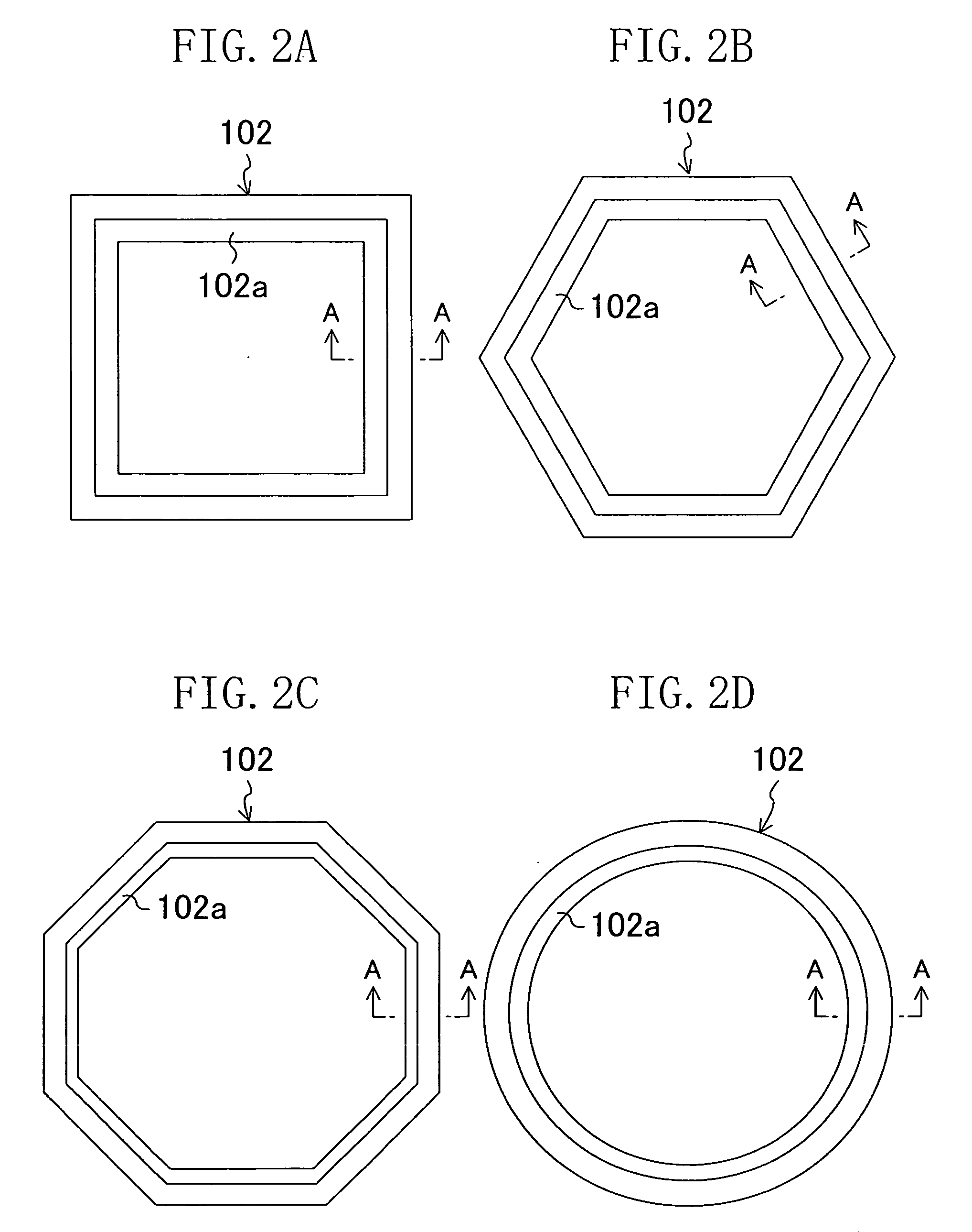
[0064] In a process chamber 101 of the rapid thermal processing system shown in FIG. 1A, the end (edge) of a substrate 100 to be processed is carried by an annular substrate carrier 102. The substrate carrier 102 is placed in the bottom portion within the process chamber 101 with a rotating unit 103 interposed therebetween. The upper portion of the process chamber 101 is provided with a heating unit 104, and an area within the process chamber 101 located under the substrate 100 is provided with a plurality of optical pyrometers 105 so that the opt...

second embodiment

[0078] A rapid thermal processing system according to a second embodiment of the present invention will be described below with reference to the accompanying drawings.

[0079] The whole structure of the rapid thermal processing system according to the second embodiment is similar to that of the first embodiment shown in FIG. 1A. To be more specific, in a process chamber 101 of the rapid thermal processing system shown in FIG. 1A, the end (edge) of a substrate 100 to be processed is carried by an annular substrate carrier 102. The substrate carrier 102 is placed in the bottom portion within the process chamber 101 with a rotating unit 103 interposed therebetween. The upper portion of the process chamber 101 is provided with a heating unit 104, and an area within the process chamber 101 located under the substrate 100 is provided with a plurality of optical pyrometers 105 so that the optical pyrometers 105 are not in direct contact with the substrate 100. The heating unit 104 and the o...

third embodiment

[0094] A rapid thermal processing system according to a third embodiment of the present invention will be described below with reference to the accompanying drawings.

[0095] The whole structure of the rapid thermal processing system according to the third embodiment is similar to that of the first embodiment shown in FIG. 1A. To be more specific, in a process chamber 101 of the rapid thermal processing system shown in FIG. 1A, the end (edge) of a substrate 100 to be processed is carried by an annular substrate carrier 102. The substrate carrier 102 is placed in the bottom portion within the process chamber 101 with a rotating unit 103 interposed therebetween. The upper portion of the process chamber 101 is provided with a heating unit 104, and an area within the process chamber 101 located under the substrate 100 is provided with a plurality of optical pyrometers 105 so that the optical pyrometers 105 are not in direct contact with the substrate 100. The heating unit 104 and the opt...


PUM

PropertyMeasurementUnit
temperatureaaaaaaaaaa
pressureaaaaaaaaaa

Abstract

Using a rapid thermal processing system provided with a substrate carrier supporting a substrate and having oxidation resistance, rapid thermal processing is carried out on the substrate.

Description

CROSS-REFERENCE TO RELATED APPLICATIONS [0001] This application claims priority under 35 U.S.C. § 119 on Patent Application No. 2003-408769 filed in Japan on Dec. 8, 2003, the entire contents of which are hereby incorporated by reference. BACKGROUND OF THE INVENTION [0002] (a) Fields of the Invention [0003] The present invention relates to rapid thermal processing systems for carrying out rapid thermal processing on a substrate, methods for manufacturing such a system, and methods for adjusting the temperature of the substrate in the rapid thermal processing system. [0004] (b) Description of Related Art [0005] Recently, miniaturization and high degree of integration of semiconductor elements have rapidly been developed, and the diameter of a substrate (wafer) has increasingly become greater. Accompanied with these trends, a conventional batch processing for processing a plurality of substrates at a time is shifting to a single wafer processing. [0006] In a thermal processing process...

Claims


Application Information

Patent Timeline
Patent Type & Authority Applications(United States)
IPC IPC(8): H01L21/683C23C16/00H01L21/00H01L21/26H01L21/68
CPCH01L21/67248H01L21/67109
Inventor KUBO, HIROKO
Owner PANASONIC CORP
Why Eureka
Try Eureka