Medical devices and EFAB methods and apparatus for producing them

a technology of medical devices and efab, applied in the field of miniature medical devices, can solve the problems of destroying the separation of masking materials from the substrate, and achieve the effect of reducing the risk of injury

Inactive Publication Date: 2005-06-09
MICROFAB
View PDF13 Cites 60 Cited by
  • Summary
  • Abstract
  • Description
  • Claims
  • Application Information

AI Technical Summary

Benefits of technology

[0040] Further aspects of the invention will be understood by those of skill in the art upon reviewing the teachings herein. Other aspects of the invention may involve combinations of the above noted aspects of the invention. Other aspects of the invention may involve apparatus that can be used in implementing one or more of the above method aspects of the invention. These other aspects of the invention may provide various combinations of the aspects presented above as well as provide other configurations, structures, functional relationships, and processes that have not been specifically set forth above.

Problems solved by technology

The CC mask plating process is distinct from a “through-mask” plating process in that in a through-mask plating process the separation of the masking material from the substrate would occur destructively.

Method used


Image

  • Medical devices and EFAB methods and apparatus for producing them
  • Medical devices and EFAB methods and apparatus for producing them
  • Medical devices and EFAB methods and apparatus for producing them

Examples


first embodiment

[0053] In a first embodiment a micro-tweezer or retriever is formed. The retriever is depicted in FIG. 5. The retriever includes a housing 152 with normally closed fingers 154 and 156. a control shaft 162 is located within housing 152 where it may have been formed. The shaft includes a tapered end element 164 that may be used to open normally closed fingers 154 and 156. When the tapered end element 164 is pulled in direction 168, relative to housing 152, contact between tapering surfaces 166 and 158 causes the fingers 154 and 156 to spread apart. Spring elements 172 resist surfaces 158 and 166 coming into contact and thereby cause surfaces 158 and 166 to separate when pressure along direction 168 is removed thus allowing normally closed fingers 154 and 156 to return to their gripping (i.e. closed) positions. Shaft 162 may be positioned within an extended housing that abuts the backend 178 of housing 152. During use, the extended housing may extend from the body of the patient and al...

second embodiment

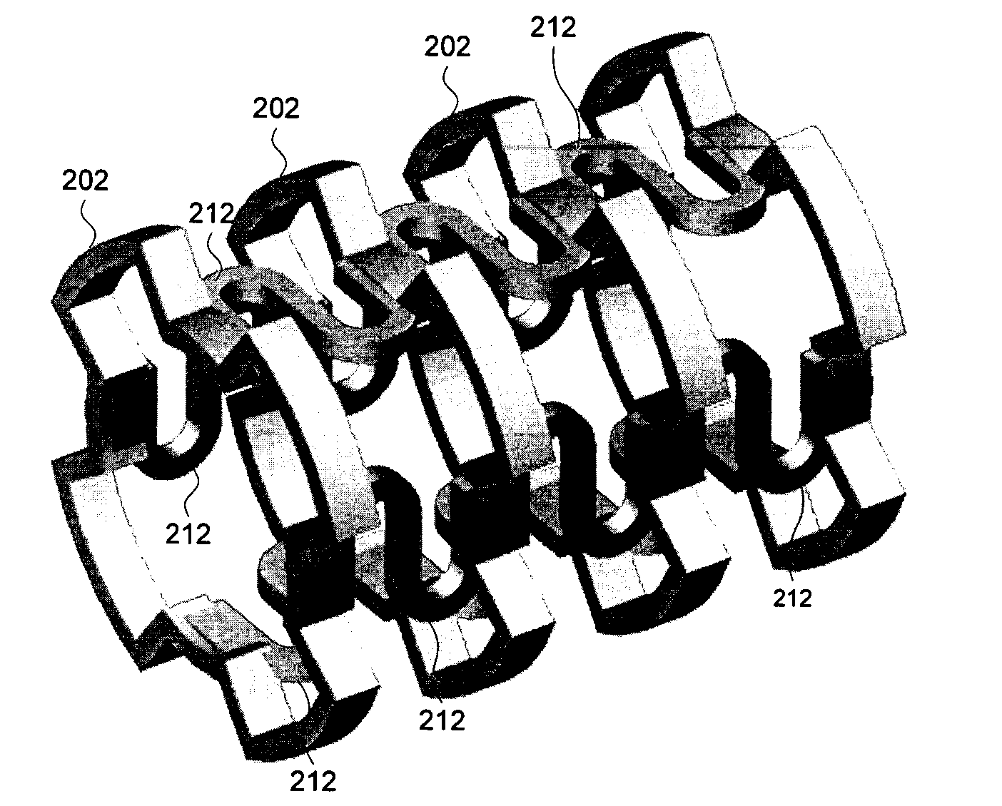
[0056] In the invention an internally expandable stent is provided. In a preferred embodiment the stent includes a number of ring-like elements 202 where the ring-like elements include outer ring elements 204 and inner ring elements 206 connected by arms 208. The ring-like elements 202 are connected to adjacent ring-like elements with flexible S-shaped members 212. In the illustrated embodiment each ring-like member 202 is connected to an adjacent ring element 202 by four S-shaped members.

[0057] In alternative embodiments fewer S-shaped elements may be used. For example, two elements on opposite sides of each ring could be used or even one S-shaped element could be used to connect successive rings. In such embodiments, the S-shaped elements may all be located on the same side of successive rings or on opposite sides of successive rings or even in a spiraling pattern from along a chain of successive rings. In some embodiments the connecting members may extend from inner ring elements...


PUM

PropertyMeasurementUnit
widthaaaaaaaaaa
widthaaaaaaaaaa
three-dimensional structureaaaaaaaaaa

Abstract

Various embodiments of the invention present miniature medical devices that may be formed totally or in part using electrochemical fabrication techniques. Sample medical devices include micro-tweezers or forceps, internally expandable stents, bifurcated or side branch stents, drug eluting stents, micro-valves and pumps, rotary ablation devices, electrical ablation devices (e.g. RF devices), micro-staplers, ultrasound catheters, and fluid filters. In some embodiments devices may be made out of a metal material while in other embodiments they may be made from a material (e.g. a polymer) that is molded from an electrochemically fabricated mold. Structural materials may include gold, platinum, silver, stainless steel, titanium or pyrolytic carbon-coated materials such as nickel, copper, and the like.

Description

RELATED APPLICATIONS [0001] This application claims benefit to U.S. Provisional Patent application No. 60 / 422,007, filed Oct. 29, 2002, which is incorporated herein by reference as if set fourth in full.FIELD OF THE INVENTION [0002] The present invention relates generally to the field of miniature medical devices which may be formed by Electrochemical Fabrication. BACKGROUND [0003] A technique for forming three-dimensional structures (e.g. parts, components, devices, and the like) from a plurality of adhered layers was invented by Adam L. Cohen and is known as Electrochemical Fabrication. It is being commercially pursued by Microfabrica Inc. (formerly MEMGen® Corporation) of Burbank, Calif. under the name EFAB™. This technique was described in U.S. Pat. No. 6,027,630, issued on Feb. 22, 2000. This electrochemical deposition technique allows the selective deposition of a material using a unique masking technique that involves the use of a mask that includes patterned conformable mate...

Claims


Application Information

Patent Timeline
Patent Type & Authority Applications(United States)
IPC IPC(8): A61F2/06B81C1/00
CPCA61F2/91A61F2002/065Y10T428/13A61F2210/0076A61F2230/0058A61F2230/006
Inventor COHEN, ADAM L.
Owner MICROFAB
Why Eureka
Try Eureka