Method of improving weld quality

a technology of weld quality and method, applied in the field of welding process, can solve the problems of limited success in joining aluminum or magnesium substrates, aluminum presents several metallurgical difficulties, laser welding suffers from problems with reflective materials, etc., and achieves the effects of slow solidification of the molten weld trough, wide temperature distribution, and reduced porosity

Inactive Publication Date: 2005-06-09
GM GLOBAL TECH OPERATIONS LLC +1
View PDF8 Cites 42 Cited by
  • Summary
  • Abstract
  • Description
  • Claims
  • Application Information

AI Technical Summary

Benefits of technology

[0008] The present invention meets these needs by providing an improved method of laser welding of lightweight metal materials, such as aluminum and magnesium, that uses a supplemental heating means to heat the lightweight metal materials and thereby widen the temperature distribution around a molten weld trough so as to slow solidification of the molten weld trough and thereby reduce porosity within a resultant solidified weld bead.

Problems solved by technology

Such body panels, however, are increasingly being produced from lightweight sheet metals such as aluminum and magnesium, which are traditionally not conducive to high production laser welding.
While laser welding is widely successful in joining steel substrates, it has met with limited success in joining aluminum or magnesium substrates.
Laser welding involves light beams and, thus, laser welding suffers from problems with reflective material such as aluminum.
Additionally, aluminum presents several metallurgical difficulties because some common alloying elements therein, like zinc and magnesium, have very high vapor pressures and, thus, tend to boil out of a molten weld trough under typical laser welding conditions.
Besides depleting the alloy content of the weld, this “boil out” condition leads to keyhole instability and high levels of porosity in laser welds, particularly where the depth of the keyhole is greater than the width of the weld bead.
Also, lap-welded joints have a particular problem with out-gassing of coatings or contaminants on the aluminum substrates that leads to weld bead porosity.
Filler metal, unfortunately, is difficult to use with lasers because it is very difficult to get filler metal wire into the tiny melt zones that most lasers produce.
Furthermore, attempts to optimize the welding heat input by pulsing the laser, and thereby controlling the rate of solidification of the molten weld trough, have not met with good results.
In practice, however, this process of intrinsically regulating the temperature of the molten weld trough by pulsing the laser simply does not solve the problem of porosity.

Method used


Image

  • Method of improving weld quality
  • Method of improving weld quality
  • Method of improving weld quality

Examples


Embodiment Construction

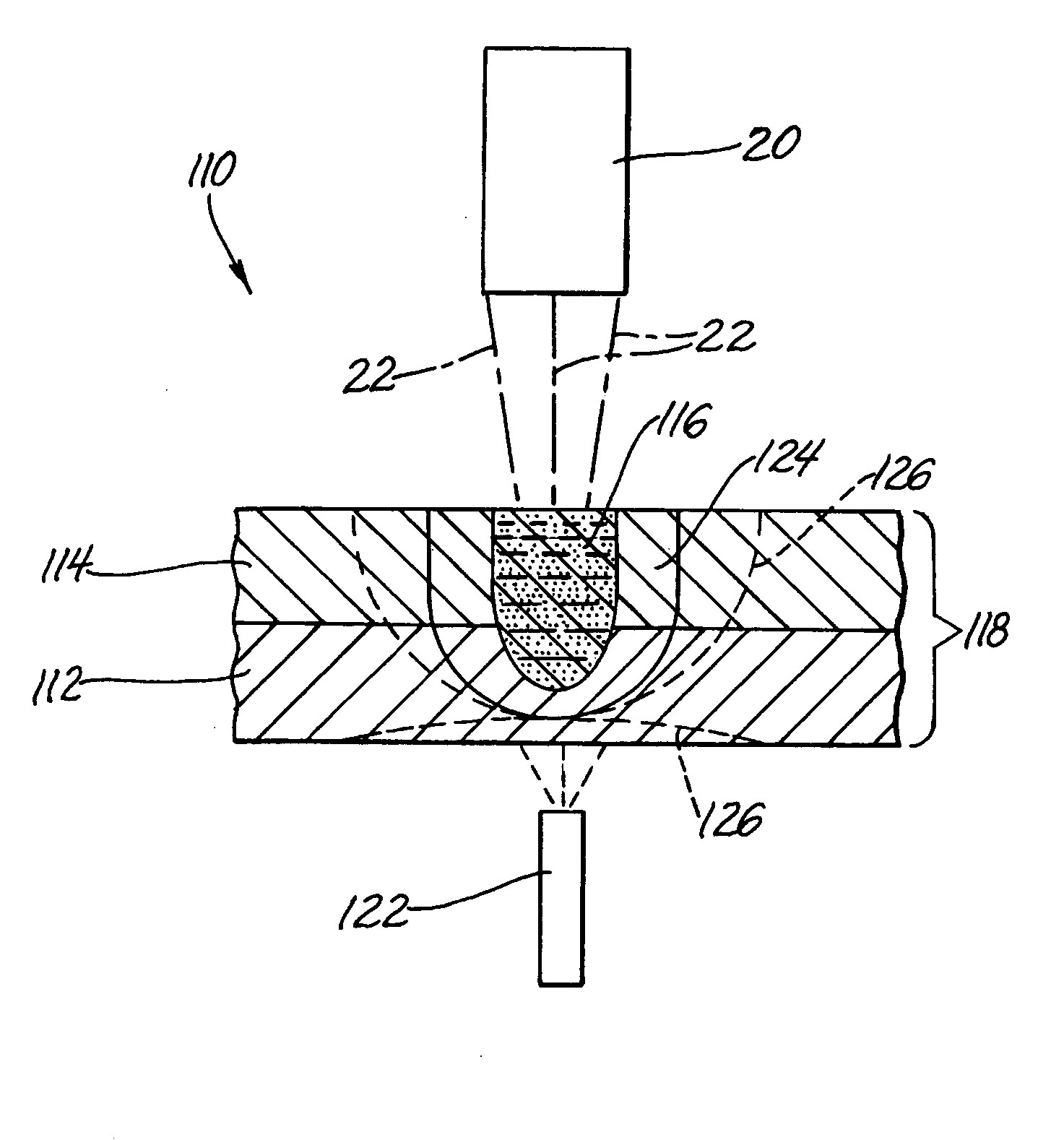
[0018] In general, the present invention provides a method of improving weld quality in laser welding of aluminum or magnesium members wherein a heating means, which is separate from a welding laser, is used to heat the aluminum components so as to slow solidification of a molten weld trough created by the welding laser and thereby reduce porosity within a resultant weld bead. The term member as used herein encompasses components, sheet material, and the like. The present invention may best be understood in contrast to prior art aluminum laser welding processes.

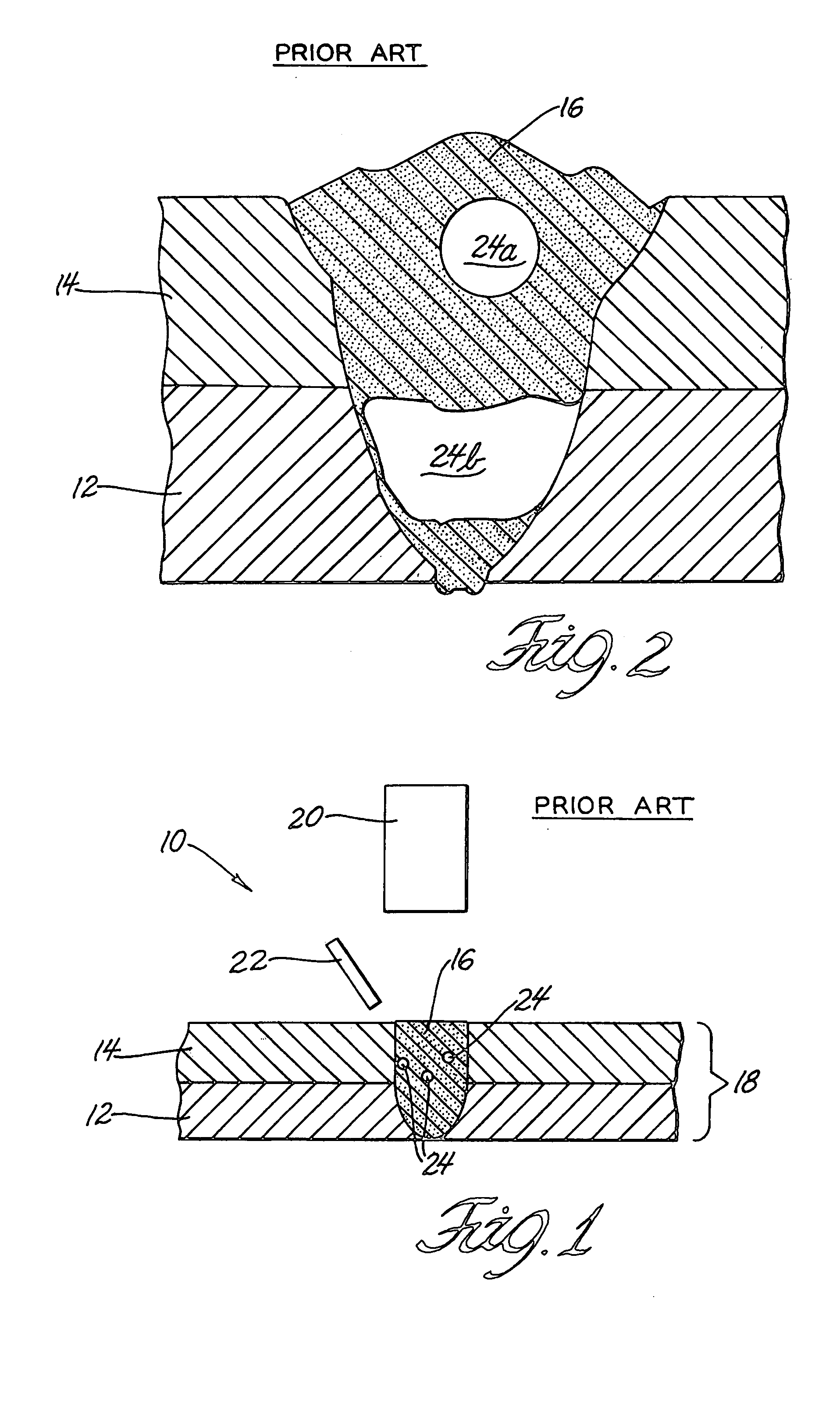
[0019] Referring specifically now to the Figures, there is illustrated in FIG. 1 a laser welding setup 10 according to the prior art. The welding setup includes a lower sheet 12 composed of aluminum, an upper sheet 14 also composed of aluminum, and a weld 16 joining the upper and lower sheets 14, 12. The weld 16 is shown in cross section and may either be a cross section of a linear bead of a weld bead or may be a cross sect...


PUM

PropertyMeasurementUnit
diameteraaaaaaaaaa
diameteraaaaaaaaaa
timeaaaaaaaaaa

Abstract

A method of improving weld quality between aluminum members by slowing the rate of solidification of a molten weld trough into solidified material. Upper and lower aluminum members are positioned together in contact between facing surfaces thereof to expose a first outer surface of the upper aluminum member to laser irradiation. A welding laser beam is moved in a path over the first outer surface, wherein the welding laser beam has an energy and width to progressively melt a trough of molten metal to a depth through the upper aluminum member and into the lower aluminum member. The molten metal in the trough has a void filled with gas, and the molten metal re-solidifies into re-solidified metal after the passage of the welding laser beam. An area in and around the trough is heated to slow the rate of solidification of the molten metal into the re-solidified metal, thereby preventing entrainment of the gas within the re-solidified metal.

Description

TECHNICAL FIELD [0001] The present invention generally pertains to a welding process. More particularly, this invention pertains to a method of improving weld quality in laser welding of lightweight metal components, such as those composed of magnesium or aluminum. A separate heating means is used to raise the temperature of the lightweight metal components and thereby widen a heat-affected weld zone around a molten weld trough so as to slow solidification of the molten weld trough and thereby reduce porosity within a resultant weld bead. BACKGROUND OF THE INVENTION [0002] Use of lasers in industrial manufacturing environments is becoming increasingly widespread and such use includes welding of automotive body panels. Such body panels, however, are increasingly being produced from lightweight sheet metals such as aluminum and magnesium, which are traditionally not conducive to high production laser welding. [0003] In general, laser welding is a joining process wherein coalescence of...

Claims


Application Information

Patent Timeline
Patent Type & Authority Applications(United States)
IPC IPC(8): B23K26/24B23K26/32
CPCB23K26/246B23K2203/10B23K26/3226B23K26/32B23K26/244B23K2103/10B23K26/067
Inventor WANG, PEI-CHUNGTSAI, HAI-LUNGMENASSA, ROLAND J.
Owner GM GLOBAL TECH OPERATIONS LLC
Why Eureka
Try Eureka