
Suspension board with circuit

a suspension board and circuit technology, applied in the direction of maintaining head carrier alignment, instruments, integrated arm assemblies, etc., can solve the problems of affecting the stability of the suspension board, the damage of the conductor layer and the pad portion exposed in the flying lead portion, and the damage of the conductor layer and the pad portion in the additive process, so as to reduce the risk of damage

Inactive Publication Date: 2005-06-09
NITTO DENKO CORP
View PDF4 Cites 52 Cited by
  • Summary
  • Abstract
  • Description
  • Claims
  • Application Information

AI Technical Summary

Benefits of technology

[0009] It is the object of the invention to provide a suspension board with circuit having a conductor layer formed in the form of a fine wiring circuit pattern by an additive process, while providing a reduced risk of damage and breaking of the conductor layer in a flying lead portion.
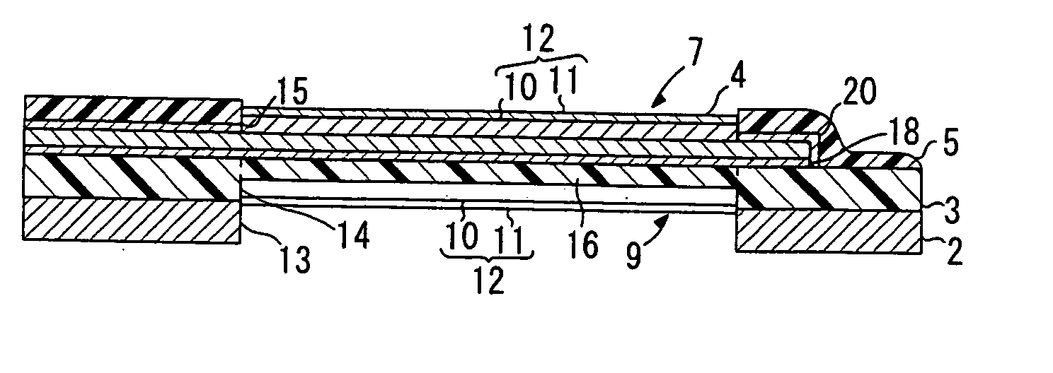
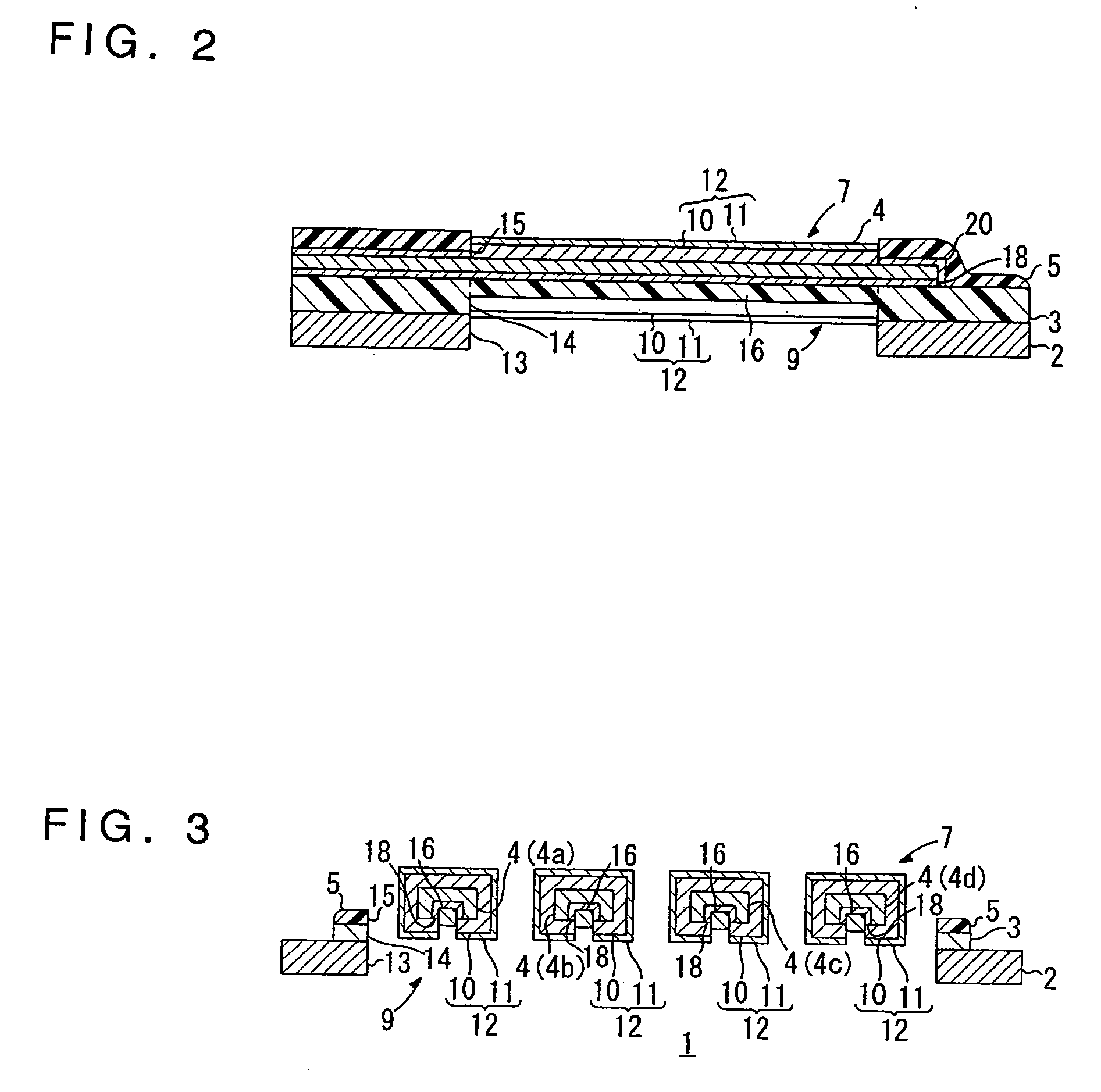
[0011] In this suspension board with circuit, the insulating layer is included as the reinforcing portion for reinforcing the conductor layer in the flying lead portion. This can provide the result that even when the conductor layer in the flying lead portion is physically damaged directly when the conductor layer is formed in the form of a fine wiring circuit pattern via various production processes of the additive process, fatal damage or breaking of the conductor layer can be prevented by the reinforcement provided by the reinforcing portion. This can produce the suspension board with circuit wherein while the conductor layer is formed in the form of a fine wiring circuit pattern, the fatal damage or breaking of the conductor layer in the flying lead portion can be effectively prevented, thus providing improvement in reliability of the suspension board with circuit for use.
[0013] The arrangement of the reinforcing portion being arranged along the longitudinal direction of the conductor layer can permit reliable reinforcement of the conductor layer over the longitudinal dimension of the conductor layer in the flying lead portion. It can also provide the result that the reinforcing portion can be formed continuously from the insulating layer.

Problems solved by technology

In the suspension board with circuit including the flying lead portion, when the conductor layer is formed in the wiring circuit pattern by the additive process, there is a possibility that the conductor layer and pad portion exposed in the flying lead portion may be damaged in the additive process.
This is because since the additive process involves various production processes including the treatment process using a treatment agent and the washing process using washing water, there is a possibility that the conductor layer and pad portion exposed in the flying lead portion may be physically damaged directly, so that the conductor layer and the pad portion may be broken in the processes of the additive process.
Particularly in the case of the conductor layer exposed in the flying lead portion being required to be thin, the possibility of such a breaking will increase.

Method used


Image

  • Suspension board with circuit
  • Suspension board with circuit
  • Suspension board with circuit

Examples


example 1

[0129] The following processes were carried out using a roll-to-roll process, to obtain a suspension board with circuit.

[0130] A supporting board of a stainless foil of 300 mm wide, 20 cm thick, and 120 m long was prepared (Cf. FIG. 4(a)). Then, after a solution of polyamic acid resin was coated over the entire surface of the supporting board, the coated resin was heated at 100° C., to form a coating of the polyamic acid resin having a thickness of 25 μm (Cf. FIG. 4(b)). Then, the coating thus formed was exposed to light of 720 mJ / cm2 through a gradation exposure mask comprising a light shielding part (whose light transmission is 0%), a semi-transparent part (whose light transmission is 50%), and a light transmission part (whose light transmission is 100%) and was heated at 180° C. Then, it was developed using alkaline developer (Cf. FIG. 4(c)). Thereafter, the coating was cured at a highest temperature of 420° C., whereby the insulating base layer of polyimide resin was formed wit...

example 2

[0140] The following processes were carried out using a roll-to-roll process, to obtain a suspension board with circuit.

[0141] A supporting board of a stainless foil of 300 mm wide, 20 μm thick, and 120 m long was prepared (Cf FIG. 10(a)). Then, after a solution of polyamic acid resin was coated over the entire surface of the supporting board, the coated resin was heated at 100° C., to form a coating of the polyamic acid resin having a thickness of 25 μm (Cf. FIG. 10(b)). Then, the coating thus formed was exposed to light of 720 mJ / cm2 through a photo mask and was heated at 180° C. Then, it was developed using alkaline developer (Cf FIG. 10(c)). Thereafter, the coating was cured at a highest temperature of 420° C., whereby the insulating base layer of polyimide resin was formed with a predetermined pattern (Cf FIG. 10(d)). The thickness of the insulating base layer thus formed was 10 μm.

[0142] Sequentially, a thin chromium film having a thickness of 400 Å and a thin copper film ha...


PUM

PropertyMeasurementUnit
widthaaaaaaaaaa
widthaaaaaaaaaa
widthaaaaaaaaaa

Abstract

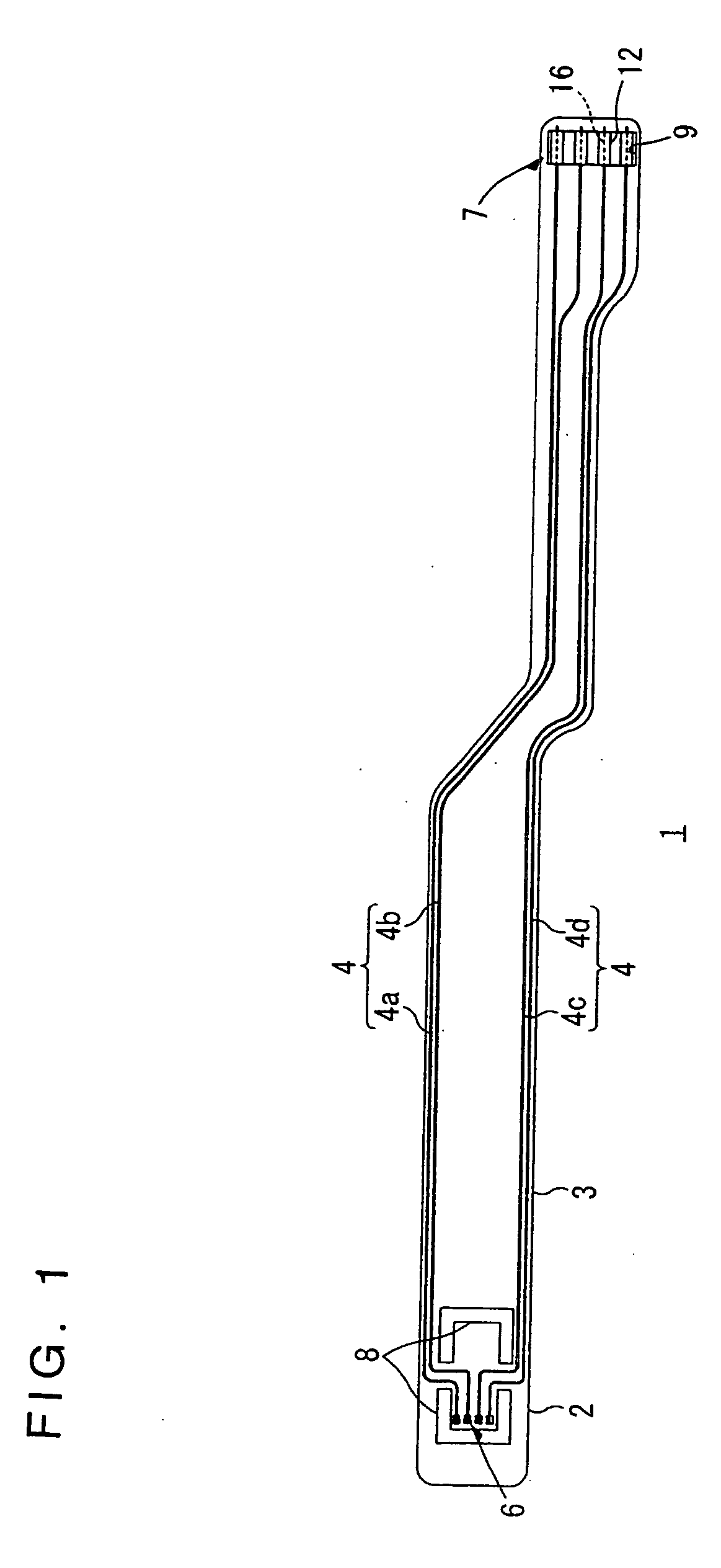
A suspension board with circuit having a conductor layer formed in the form of a fine wiring circuit by an additive process, while providing a reduced risk of damage and breaking of the conductor layer in a flying lead portion. The suspension board with circuit comprises a supporting board 2, an insulating base layer 3 formed on the supporting board 2, a conductor layer 4 formed on the insulating base layer 3, an insulating cover layer 5 formed on the conductor layer 4, and a flying lead portion 9 in which a supporting-board-side opening 13, a base-layer-side opening 14, and a cover-layer-side opening 15 are formed so that both sides of the conductor layer 4 can be exposed therefrom. A reinforcing portion 16 or 23 for reinforcing the conductor layer 4 formed continuously from at least either of the insulating base layer 3 and the insulating cover layer 5 along the longitudinal direction of the conductor layer 4 is included in the flying lead portion 9.

Description

BACKGROUND OF THE INVENTION [0001] 1. Field of the Invention [0002] The present invention relates to a suspension board with circuit, and more particularly, to a suspension board with circuit used for a hard disc drive. [0003] 2. Description of the Prior Art [0004] A suspension board with circuit used for a hard disc drive is a wired circuit board comprising a suspension board supporting a magnetic head and a wiring circuit pattern, integrally formed on the suspension board, for connecting between the magnetic head and a read / write board to which read / write signals read and written by the magnetic head are transmitted. The suspension board with circuit is now being in widespread use in that it can support the magnetic head, with a minute interval between the magnetic head and a magnetic disk held against an airflow generated when the magnetic head and the magnetic disk run relative to each other, so that it can well maintain the floatation of the magnetic head mounted on the suspens...

Claims


Application Information

Patent Timeline
Patent Type & Authority Applications(United States)
IPC IPC(8): G11B5/00G11B5/60G11B5/012G11B5/48G11B21/00G11B21/02G11B21/21H05K1/05H05K1/11H05K3/24H05K3/28H05K3/40
CPCG11B5/486H05K1/056H05K3/243H05K2201/0969H05K3/4092H05K2201/0394H05K3/28G11B5/484G11B21/02
Inventor KANAGAWA, HITOKIFUNADA, YASUHITOOOSAWA, TETSUYA
Owner NITTO DENKO CORP
Learn More