Eureka AIR delivers breakthrough ideas for toughest innovation challenges, trusted by R&D personnel around the world.

Power supply system

a power supply system and power supply technology, applied in the field of power supply systems, can solve the problems of self-commutated converters or active front end, high cost and complexity, and is employed, and still of the line-commutated, free-running type, which is expensive and complex, and achieves the effects of improving the energy balance of the power supply system, reducing the cost of operation, and discharging energy from load

Inactive Publication Date: 2005-06-09
SIEMENS AG
View PDF1 Cites 56 Cited by
  • Summary
  • Abstract
  • Description
  • Claims
  • Application Information

AI Technical Summary

Benefits of technology

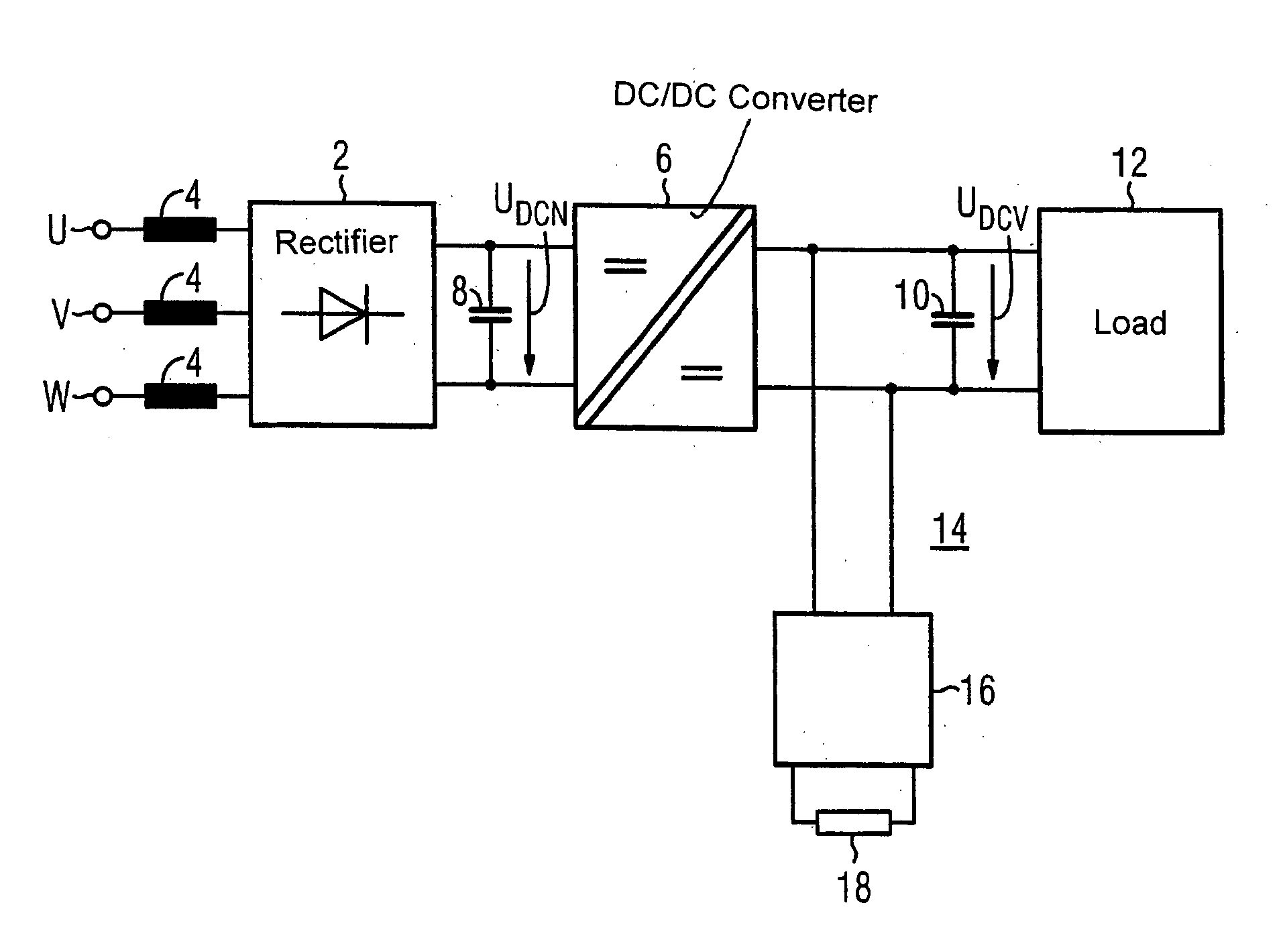
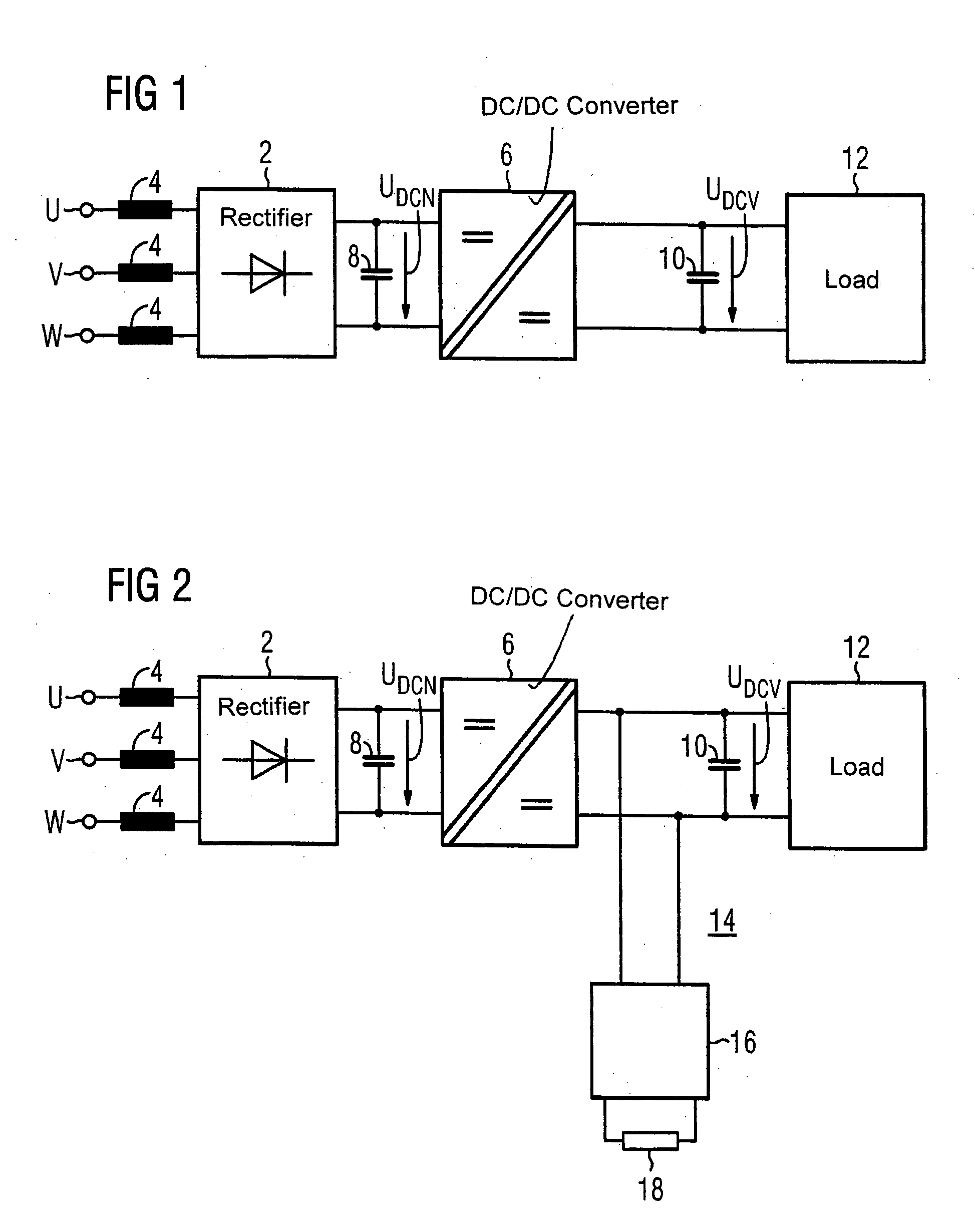
[0013] As a consequence of the symmetric configuration of the DC / DC converter, the secondary side of the DC / DC converter is identical to the primary side, so that the converter is now configured for power feedback, making the entire power supply system capable of energy recovery. A brake circuit is therefore no longer required to dissipate energy from the load. Energy returned from the load to the power line significantly improves the energy balance of the power supply system. The power supply system of the invention is also significantly less expensive than a conventional power supply device with a brake circuit.
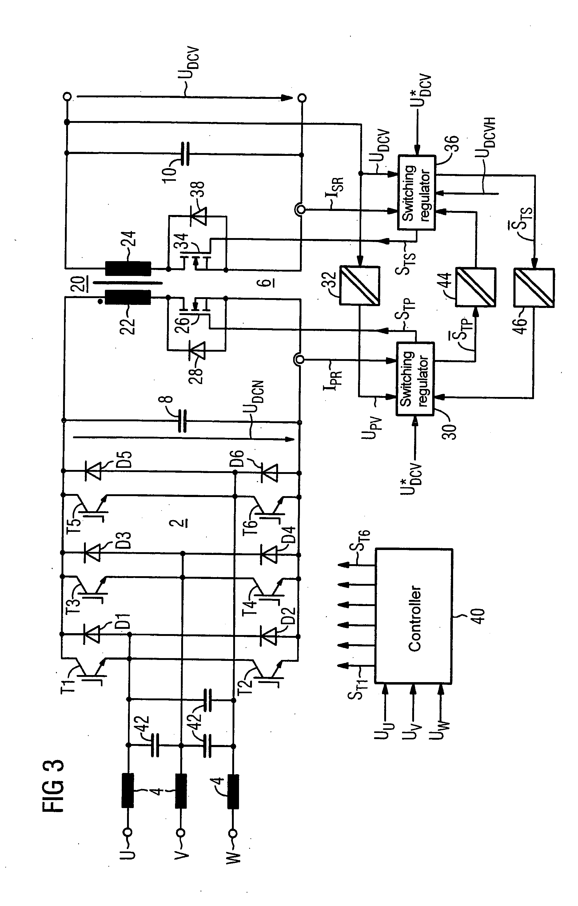
[0014] According to another feature of the present invention, the DC / DC converter can include a primary switching regulator and a secondary switching regulator, wherein an output of the primary (secondary) switching regulator is connected to a complementary control input of the secondary (primary) switching regulator with an isolated potential. An electronically controllable switch on the primary or secondary side is thereby turned on during the conducting phase of a corresponding diode to conduct electric current. This switch has a smaller forward voltage than the diode, which reduces the dissipated power and improves the efficiency.

Problems solved by technology

However, a self-commutated converter or Active Front End is expensive and complex and is employed only if stringent requirements are imposed on line feedback and if the dissipated braking power is very high.
Although the line-side converter is now capable of conducting electric current in both current directions, it is still of the line-commutated, free-running type which is expensive and complex.
However, even if the rectifier can conduct current in both directions, a brake circuit is still required with this conventional embodiment, because the DC / DC converter 6 is not configured to return electric energy from the load to the DC side of the rectifier.

Method used


Image

  • Power supply system
  • Power supply system
  • Power supply system

Examples


Embodiment Construction

[0022] Throughout all the Figures, same or corresponding elements are generally indicated by same reference numerals. These depicted embodiments are to be understood as illustrative of the invention and not as limiting in any way. It should also be understood that the drawings are not necessarily to scale and that the embodiments are sometimes illustrated by graphic symbols, phantom lines, diagrammatic representations and fragmentary views. In certain instances, details which are not necessary for an understanding of the present invention or which render other details difficult to perceive may have been omitted.

[0023] This is one of two applications both filed on the same day. Both applications deal with related inventions. They are commonly owned but have different inventive entity. Both applications are unique, but incorporate the other by reference. Accordingly, the following U.S. patent application is hereby expressly incorporated by reference: “DRIVE SYSTEM”.

[0024] Turning no...


PUM


Abstract

An electric power supply system includes a rectifier with an input connected to a power line and a DC output connected to a DC / DC converter. Two buffer capacitors are connected across the input and output, respectively, of the DC / DC converter. The output of the rectifier includes a plurality of diodes. An electronically controllable switch is electrically connected in parallel with a corresponding diode of the rectifier. A controller receives an input signal from a phase voltage of the power line and provides control signals to the controllable switches. The DC / DC converter is constructed symmetrically. This configuration results in a more cost-effective power supply system with an improved energy balance.

Description

CROSS-REFERENCES TO RELATED APPLICATIONS [0001] This application claims the priority of German Patent Application, Serial No. 103 56 514.0, filed Dec. 3, 2003, pursuant to 35 U.S.C. 119(a)-(d). BACKGROUND OF THE INVENTION [0002] The present invention relates to a power supply system with a rectifier with an input connected to a power line and an output connected to a DC / DC converter, and more particularly to a power supply system that enables energy recovery from the DC side to the power line. [0003] Nothing in the following discussion of the state of the art is to be construed as an admission of prior art. [0004] Conventional power supply systems that power a load from a single-phase or three-phase power line can include a rectifier connected to a DC / DC converter that supplies DC current to the load. If the load has to be braked, i.e. kinetic energy of the load must be dissipated, a brake resistor is typically used that converts the kinetic energy into heat. One exemplary conventio...

Claims


Application Information

Patent Timeline
Patent Type & Authority Applications(United States)
IPC IPC(8): H02M3/335H02M3/337H02M7/219H02M7/757
CPCH02M3/33592Y02B70/1475H02M7/219H02M3/3376Y02B70/10
Inventor GAKSCH, SUSANNE
Owner SIEMENS AG
Why Eureka
Eureka Blog
Learn More