Optical collimator-use lens component, optical collimator, and method of assembling these

a technology of optical collimator and lens component, which is applied in the direction of optics, instruments, optical light guides, etc., can solve the problem of being unable to obtain the desired coupling efficiency of optical signals, and achieve the effect of high coupling efficiency and high-quality communication performan

Inactive Publication Date: 2005-06-09
NIPPON ELECTRIC GLASS CO LTD
View PDF7 Cites 17 Cited by
  • Summary
  • Abstract
  • Description
  • Claims
  • Application Information

AI Technical Summary

Benefits of technology

[0056] Further, the distance between the end surface of the optical fiber and the translucent spherical surface of the partially spherical lens may be reduced from an optimum value calculated from the refractive index of the partially spherical lens and a spherical radius of the translucent spherical surface and may be set so that a beam waist position falls within the range of a predetermined value ±5 mm within a substantially required working distance. With this construction, it becomes possible to transmit a collimated beam of emission light with high coupling efficiency. As a result, it becomes possible to maintain high-quality communication performance.

Problems solved by technology

In this case, the distribution of beam intensity of the emission light L is decentered and it becomes impossible to obtain a desired coupling efficiency of an optical signal.

Method used


Image

  • Optical collimator-use lens component, optical collimator, and method of assembling these
  • Optical collimator-use lens component, optical collimator, and method of assembling these
  • Optical collimator-use lens component, optical collimator, and method of assembling these

Examples


Embodiment Construction

[0071] An embodiment of the present invention will now be described with reference to the accompanying drawings.

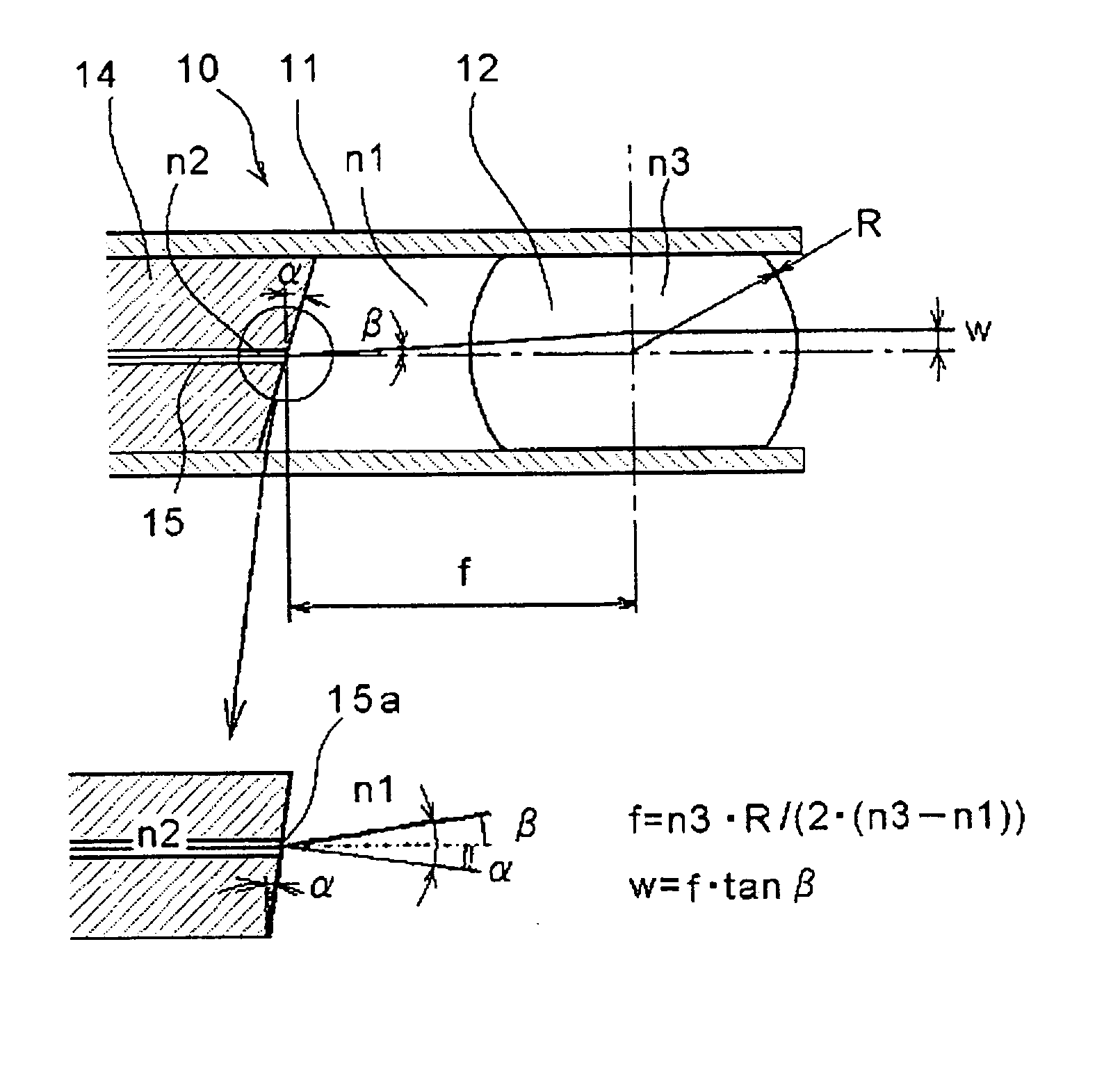
[0072] As shown in FIG. 4, an optical collimator-use lens component 10 in this embodiment includes: a phosphor-bronze-made or stainless-made split sleeve 11 that has a linear split portion 11b and a through portion 11c, is 1.60 mm in outer diameter, is 1.249 mm in inner diameter of its inner hole 11d, and is 5.5 mm in total length; a partially spherical lens 12 fixed in the inner hole 11d of the split sleeve 11 so that an insertion portion 11a having a length of 2.5 mm is left; and an adhesive 13 made of an epoxy-based resin for bonding the partially spherical lens 12 to the split sleeve 11. The partially spherical lens 12 is made of optical glass LaSF015, whose refractive index is approximately uniform, and has translucent spherical surfaces 12b and 12c, whose centers of curvature R are approximately the same and radiuses of curvature are each 1.500±0.002 mm, at both end...


PUM


Abstract

Disclosed is an optical collimator-use lens component including: a thin tube; a partially spherical lens that has been fixed in an inner hole of the thin tube so that an insertion portion having a predetermined length is left, is made of glass whose refractive index is approximately uniform, and has translucent spherical surfaces, whose centers of curvature are approximately the same, at both ends of a cylindrical portion of the partially spherical lens; and an adhesive that bonds the partially spherical lens to the thin tube. An axial deviation amount between a center axis of the thin tube and an optical axis of the partially spherical lens is 5 μm or less. When a capillary tube, in whose inner hole an optical fiber has been fixed and whose axial deviation amount between an outer peripheral surface of the capillary tube and a core center of an end surface of the optical fiber is 1.5 μm or less, is inserted into the insertion portion of the thin tube and the end surface of the optical fiber is fixed at a position at which a distance of the end surface to a focal point position of the partially spherical lens becomes ±40 μm or less, emission light has an emission light bend of 0.2° or less with respect to the center axis of the thin tube.

Description

BACKGROUND OF THE INVENTION [0001] The present invention relates to an optical collimator-use lens component, an optical collimator, a method of assembling the optical collimator-use lens component, and a method of assembling the optical collimator, with which an optical fiber for optical communications and a lens are optically coupled to each other and emission light from the optical fiber is converted into parallel light or parallel light is condensed by the lens and is brought into incident on the optical fiber. [0002] When a high-speed and large-capacity optical fiber communications system is structured, many optical devices are used. The optical devices include: an optical device that extracts an optical signal having an arbitrary wavelength from among multiple optical signals whose wavelengths have been multiplexed; and an optical device that uses an optical crystal for matching phases of optical signals, and many optical collimators are used therein which each convert a widen...

Claims


Application Information

Patent Timeline
Patent Type & Authority Applications(United States)
IPC IPC(8): G02B6/26G02B6/32
CPCG02B6/264G02B6/327G02B6/32
Inventor SETO, TADASHIKADOMI, MASAAKITANAKA, HIROKAZUTAKEUCHI, HIROKAZUITO, SHINTARO
Owner NIPPON ELECTRIC GLASS CO LTD
Why Eureka
Try Eureka