
Spiral wound laminate wood and method for construction

a technology of spiral wound and laminate wood, applied in the field of wood products, to achieve the effect of strong laminate bonding, low axial force, and minimal thickness of glu

Inactive Publication Date: 2005-06-09
WOUND WOOD TECH
View PDF30 Cites 11 Cited by
  • Summary
  • Abstract
  • Description
  • Claims
  • Application Information

AI Technical Summary

Benefits of technology

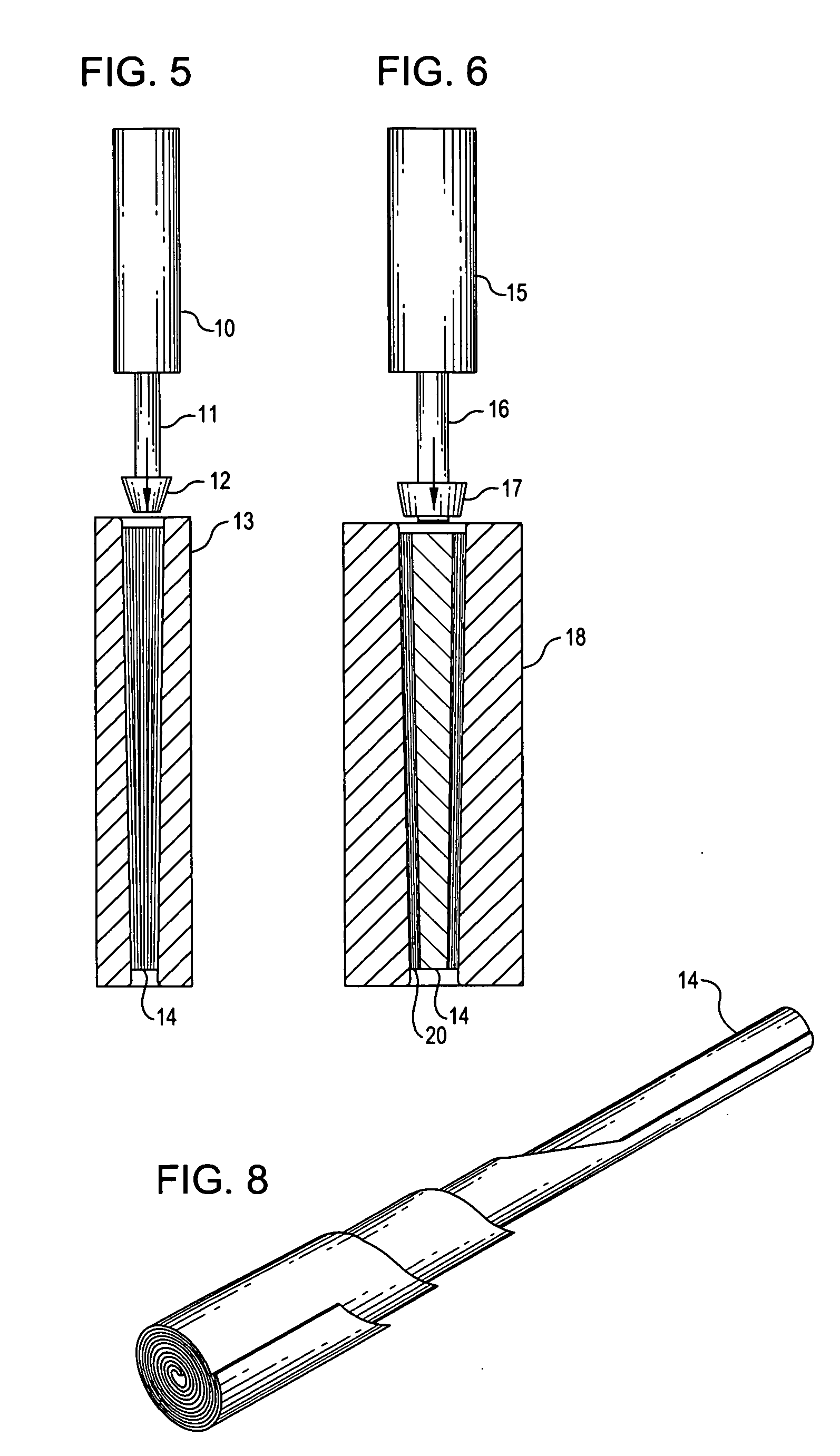
[0008] In order to compress the wood veneer into a tightly wound cylindrical cone shape, it is necessary to press the rolled assembly into a tapered die with a hydraulic or pneumatic cylinder. Other mechanical devices such as a lead screw can also be used to force the veneer into the tapered mold while the resin sets. This is done to eliminate the air voids and to minimize the glue thickness between the layers of wood to create the strongest bond. Once the glue, epoxy, or resin has cured, the spiral-wound laminated core is removed from the tapered die.
[0011] The slightly tapered die provides an ideal shape to create tremendous circumferential forces on the spiral laminate. This can be done with a very low axial force on the roll due to the great advantage of the slightly tapered mold. The large circumferential force created by the mold will eliminate air bubbles in the glue or binder and will serve to minimize glue thickness, thereby creating an extremely strong laminate bond.
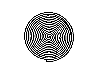
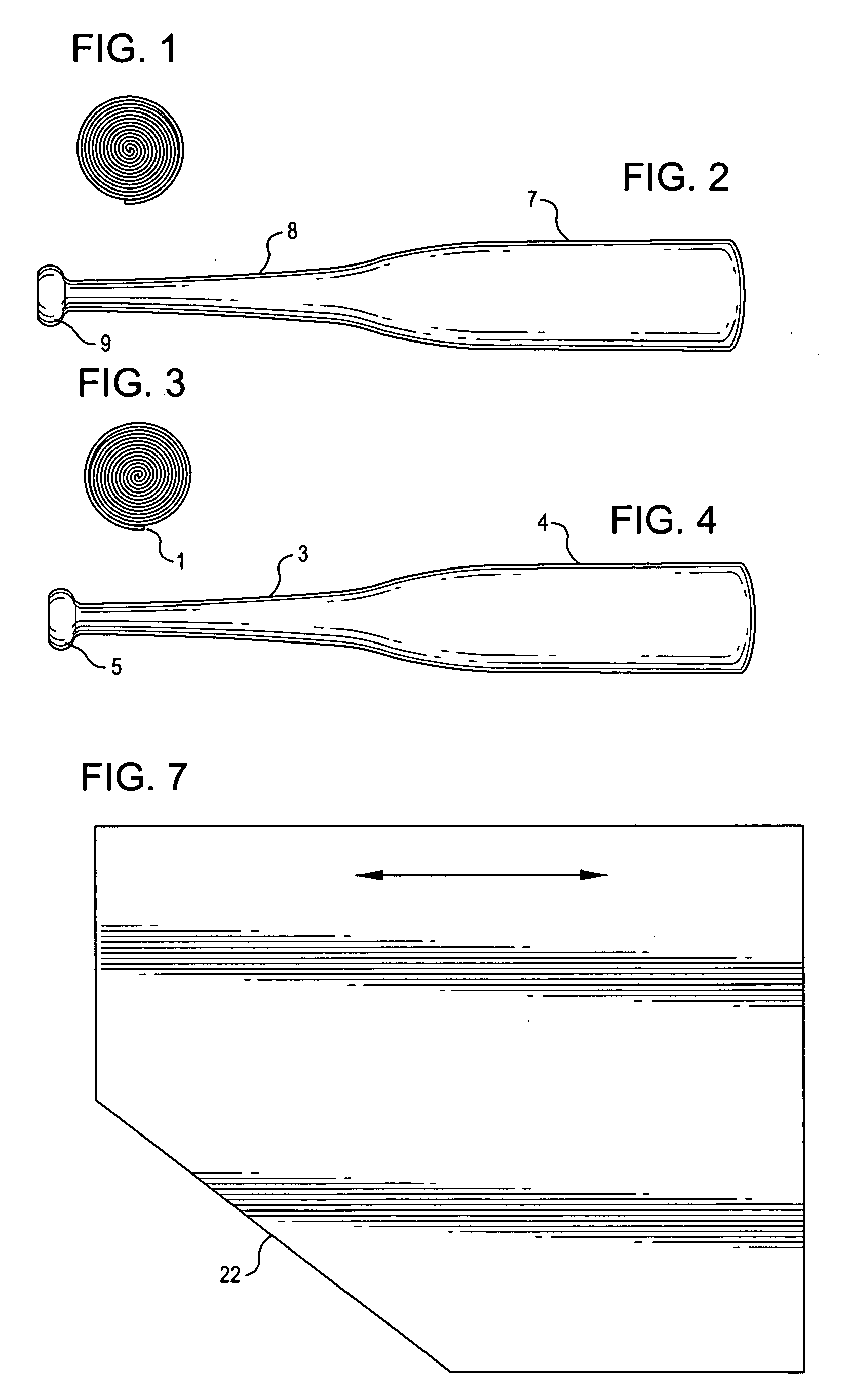
[0012] The spiral wound bat is extremely strong and has no preferred orientation of maximum strength. It can be hit from any angle, orientation, or direction without shattering and breaking. A continuously wound spiral pattern from the core of the bat to the outer surface results in a wood laminate that has exceptional strength and is uniform in all directions. Players will not have to be worried about a preferred grain orientation when using this bat as they do with conventional bats or other laminated bats.

Problems solved by technology

However, in the subsequent steps, the inner cured core is used as a tapered wedge to compress the outer veneer wrap against the outer tapered wall of the mold to a compression level just below the yield of the cellulose material of the outer veneer.

Method used


Image

  • Spiral wound laminate wood and method for construction
  • Spiral wound laminate wood and method for construction
  • Spiral wound laminate wood and method for construction

Examples


Embodiment Construction

[0034] In the following description, various embodiments of the present invention will be described. For purposes of explanation, specific configurations and details are set forth in order to provide a thorough understanding of the embodiments. However, it will also be apparent to one skilled in the art that the present invention may be practiced without the specific details. Furthermore, well-known features may be omitted or simplified in order not to obscure the embodiment being described.

[0035] The spiral wound bat or other implement will be constructed of either a single or multiple veneer sheet(s) 22 of varying thicknesses wound in a very tight spiral pattern 14 as illustrated in FIGS. 7 and 8. For ease of description, one sheet will be referenced throughout this disclosure. The veneer sheet can be cut at an angle 22 to create a slightly tapered profile 21 when rolled. The veneer sheet is then coated with a common glue, binder, epoxy or thermal set resin, rolled 14, and placed...


PUM

PropertyMeasurementUnit
lengthaaaaaaaaaa
thicknessaaaaaaaaaa
pressureaaaaaaaaaa

Abstract

A baseball bat or the like comprised of one or more continuous spiral wound layers of wood, cellulose, or other like material rolled in a spiral fashion from the center to the outermost surface. The cellulose or other material is bound to each subsequent layer with a thin layer of resin, glue, epoxy, or other binding material of adequate strength to hold the layers together for multiple impacts by a baseball or other object. This spiral wound composite roll, in its final configuration, is of comparable density, weight and balance to ash, maple or oak material commonly used in baseball bat construction. The composite roll can be machined to a shape consistent with the shape and balance of traditional baseball bats.

Description

REFERENCE TO RELATED APPLICATION [0001] This application claims the benefit of U.S. Provisional Application No. 60 / 462,086, filed Jun. 23, 2003, entitled “Spiral Wound Laminate Wood and Method for Construction,” incorporated herein by reference.TECHNICAL FIELD OF THE INVENTION [0002] The present invention relates to wood products, and more particularly to BACKGROUND OF THE INVENTION [0003] Baseball bats made of a single piece of wood are susceptible to breakage and contain a weaker and stronger plane based upon the orientation of the wood grain. Other attempts to construct laminated wooden bats resulted in the same preferred strength orientation depending upon the coarseness or orientation of the laminates. Frequently these bats fracture when a ball is hit perpendicular to the glue plane. Construction using fiberglass reinforced plastic (FRP) or other materials alters the feel and density of the bat. [0004] Spiral wound veneer construction eliminates all of these problems by providi...

Claims


Application Information

Patent Timeline
Patent Type & Authority Applications(United States)
IPC IPC(8): A63B59/06B27D1/08B27M3/22
CPCA63B59/06B27M3/22B27D1/086A63B2209/00A63B2102/18A63B59/50A63B59/52A63B60/00
Inventor BOTTEN, STANLEYMCGUIRE, DONNIE
Owner WOUND WOOD TECH
Learn More