
System and method for manipulating a catheter for delivering a substance to a body cavity

a technology of manipulating system and catheter, which is applied in the direction of multi-lumen catheter, medical insufflators, ear treatment, etc., can solve the problems of pooling and lack of containment of fluids used with irrigation and aspiration wands, inability to easily and effectively control the delivery to all or a portion of the surgical field, and difficulty in covering large areas

Active Publication Date: 2005-06-09
TRUDELL MEDICAL INT INC
View PDF99 Cites 175 Cited by
  • Summary
  • Abstract
  • Description
  • Claims
  • Application Information

AI Technical Summary

Benefits of technology

[0010] In order to address the deficiencies in the prior art, a system and method of controllably applying a substance to a body cavity for the purpose of treating or coating tissues and/or organs, and for use in the minimally invasive surgical procedures is described. The term “substance”, as used in this specification, includes, without limitation, a liquid, powder, gas, light, such as laser or ultraviolet (UV) light, or any combination thereof. The term “body cavity”, as used in this specification, includes without limitation, body cavities created through introduction of a gas into the body, as well as naturally occurring cavities in the body or organs in the body. According to a first aspect of the invention, a system for manipulating a cat...

Problems solved by technology

Among problems that physicians have encountered during diagnostic or surgical procedures, using both “open” techniques, and minimally invasive surgical techniques (e.g. laparoscopic), are numerous post procedural complications.
A problem with delivering substances to anatomical surfaces in a body cavity is the inability to easily and effectively control delivery to all or a portion of the surgical field.
Among the difficulties associated with spraying of liquids, is the pooling and lack of containment of the fluids used with irrigation and aspiration wands.
It is also difficult to cover large areas (greater than several square centimeters), and to do so without using much more medicament than is necessary.
This contributes to the cost of excessive medication, and adding to the cost and time of the surgery.
This is problematic if the aerosol needs to be directed backward towards the entry point of the shaft, since the end of the shaft is outside the patient, and would need to be positioned in the cavity in order to direct the aerosol towards the inside of the entry port.
It may also be problematic during open surgery in circumstances where the spray needs to be directed towards a target site that faces away from the surgical opening, or that is obstructed by an anatomical structure or instrumentation.
Although some devices are capable of generating radial aerosol patterns, none are capable of directing an aerosol directly backwards towards the devices point of entry into a surgical cavity.
These are likely expensive to manufacture due to the mechanical complexity involved.
The spray particles produced by current delivery devices are often quite large and have a high exit velocity from the nozzle.
As a result, they have a high inertia due to their relatively large mass and the speed with which they exit the aerosol generation nozzle.
In addition, aerodynamic factors cause these larger particles to fall more rapidly than a smaller aerosol.
This is problematic when a uniform, even deposition of aerosol is required on the top, bottom, and sides of the surgical cavity.
Finally, the large and rapidly moving particles may cause trauma if the nozzle is positioned too close to sensitive tissue.
During a minimally invasive surgical procedure within a body cavity or lumen it may not be possible or convenient to visually determine the location and direction of the aerosol generation nozzle.
As a result it may be difficult to determine which part of the cavity the aerosol is directed at.
It may also be difficult to systematically manipulate the aerosol nozzle in a pattern that creates a uniform deposition of aerosol on all cavity surfaces.

Method used


Image

  • System and method for manipulating a catheter for delivering a substance to a body cavity
  • System and method for manipulating a catheter for delivering a substance to a body cavity
  • System and method for manipulating a catheter for delivering a substance to a body cavity

Examples


Embodiment Construction

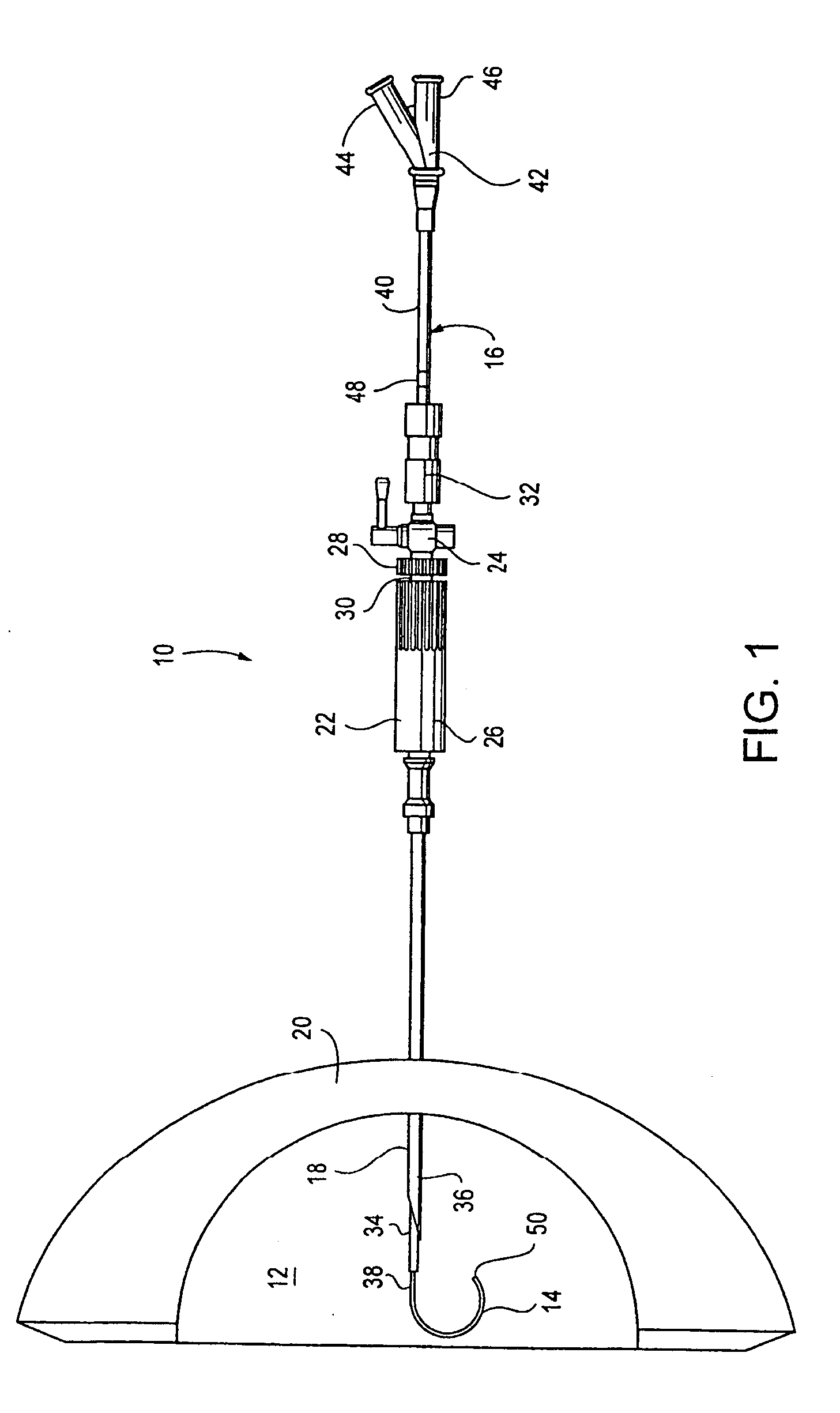
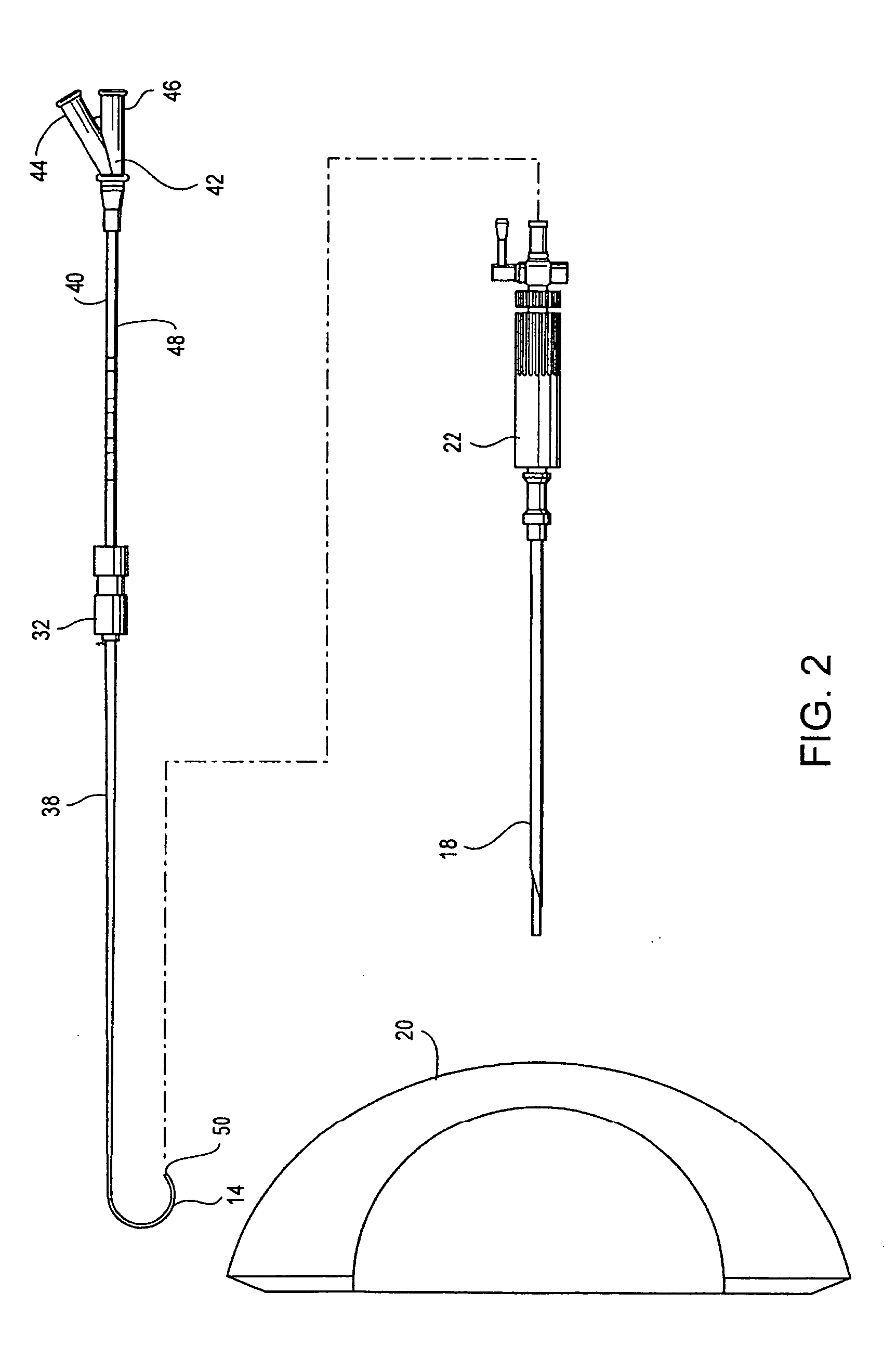
[0040] Referring to FIGS. 1-2, an embodiment of a system 10 for delivery of a substance to a body cavity 12 is shown with a shaped distal end 14 of a catheter 16 positioned in the body cavity via an introducer needle 18 piercing an abdominal wall 20. An introducer apparatus 22 releasably connects with the introducer needle 18 on one end and a valve 24 at the opposite end. The introducer apparatus 22 is composed of a first body portion 26 rotatably connected with a rotational adjustment ring 28. The rotational adjustment ring 28 may be rotatably connected with the first body portion 26 by any of a number of known frictional-fit, bearing or other adjustable rotational coupling arrangements. In one embodiment, an O-ring 30 is positioned between the first body portion 26 and rotational adjustment ring 28 to prevent leakage of any fluids. The rotational adjustment ring 28 removably attaches to the valve 24 so that the rotational adjustment ring 28 and valve 24 do not rotate with respect ...


PUM


Abstract

A system and method for adjusting a catheter to create a medicated atmosphere in an organ, or body cavity is disclosed. The system comprises a catheter, such as an aerosolization catheter, that can be manipulated during use and an introduction device for the introduction and manipulation, by rotational and / or axial positioning, of the aerosolization catheter. The method includes inserting the catheter into a body cavity via an introducer apparatus and adjusting an angle or orientation of the exit end of the catheter so that a substance provided to the catheter will be controllably applied to the body cavity at desired locations.

Description

CROSS-REFERENCE TO RELATED APPLICATION [0001] This application claims the benefit of U.S. Provisional Application No. 60 / 516,258, filed Oct. 31, 2003 the entirety of which is incorporated herein by reference.FIELD OF THE INVENTION [0002] The present invention relates to a system and method for manipulating a catheter or tube used to deliver a substance to a body cavity. BACKGROUND [0003] Recent medical studies suggest that it may be beneficial to deliver therapeutic aerosols or liquid or gas stream to anatomical surfaces within the surgical field of patients that are undergoing open or minimally invasive surgical procedures. In the case of minimally invasive surgery (MIS), the surgical field may be a natural or artificially created body cavity or lumen. Similarly, it may be desirable to deliver therapeutic aerosols to an open anatomical surface. The aerosol formulations may be delivered before a surgical procedure, after a surgical procedure, or in the absence of an adjunctive surgi...

Claims


Application Information

Patent Timeline
IPC IPC(8): A61B17/08A61F11/00A61M25/00A61M25/01A61M25/06A61M25/088A61M25/098
CPCA61M13/00A61M15/00A61M25/0032A61M25/0041A61M25/01A61M25/0105A61M2025/0681A61M25/0147A61M25/0152A61M25/0662A61M2025/0034A61M2025/0036A61M2025/0163A61M25/0113
Inventor BARAN, GEORGENUTTALL, J. MICHAEL
Owner TRUDELL MEDICAL INT INC
Learn More