Integrated heat dissipating enclosure for electronic product

Inactive Publication Date: 2005-06-16
CHAUN CHOUNG TECH
View PDF9 Cites 4 Cited by
  • Summary
  • Abstract
  • Description
  • Claims
  • Application Information

AI Technical Summary

Benefits of technology

[0005] The present invention provides an integrated heat dissipating enclosure for electronic products. A plurality of fins spaced from each other is mounted to a frame of an electronic product. As the fins are spaced from each other, the heat generated by each heat generating device can be circulated towards the external via the spaces between the fins. Therefore, the greenhouse effect is prevented.
[0006] In one embodiment of the present invention, the integrated heat dissipating enclosure for an electronic product provided by the present invention comprises a frame and a cooling cover. The frame is used to carry a plurality of devices and peripherals of the electronic product therein. The cooling cover is mounted over the frame and includes a plurality spaced fins, which are connected to each other by at least one thermal conductive pipe. Preferably, the fins are aligned with each other and arranged between a front end to a rear end of the frame, and the thermal conductive pipe extends laterally through the fins. Alternatively, the cooling cover further comprises a top heat sink panel, the fins laterally extend from two elongate sides of top heat sink panel, and the thermal pipe extend longitudinal through the fins. The thermal conductive pipe includes a heat conducting pipe or a cooling pipe. In one embodiment, the thermal conductive pipe further includes an extension in connection with an internal heat dissipation structure of the electronic product. Therefore, the heat absorbed by the internal heat dissipation structure can be easily and quickly transferred to the external. The enclosure may further comprise a pump for introducing a cooling liquid into the thermal conductive pipe to form a circulation circuit.

Problems solved by technology

The higher execution speed of the chip consequently generates more heat, and increases the temperature of the chip.
Currently, as most of the computer enclosures provide a close space for accommodation devices and peripherals, the heat generated by the heat generating devices cannot be easily dissipated to the external, and a greenhouse effect tends to occur.
However, in such manner, though heat circulation is improved, the internal devices are vulnerable for being exposed to any external structure of force.

Method used


Image

  • Integrated heat dissipating enclosure for electronic product
  • Integrated heat dissipating enclosure for electronic product
  • Integrated heat dissipating enclosure for electronic product

Examples


second embodiment

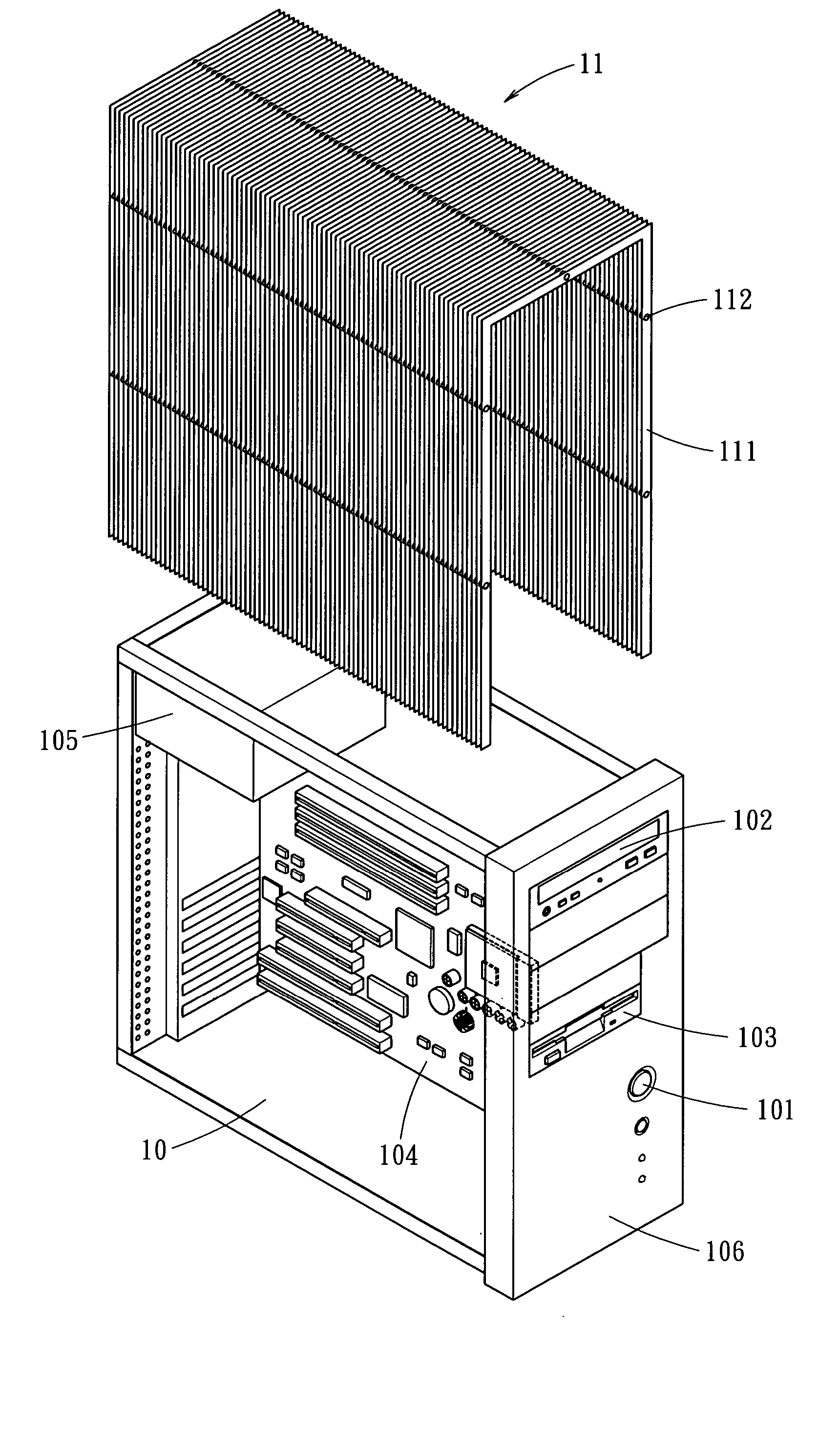
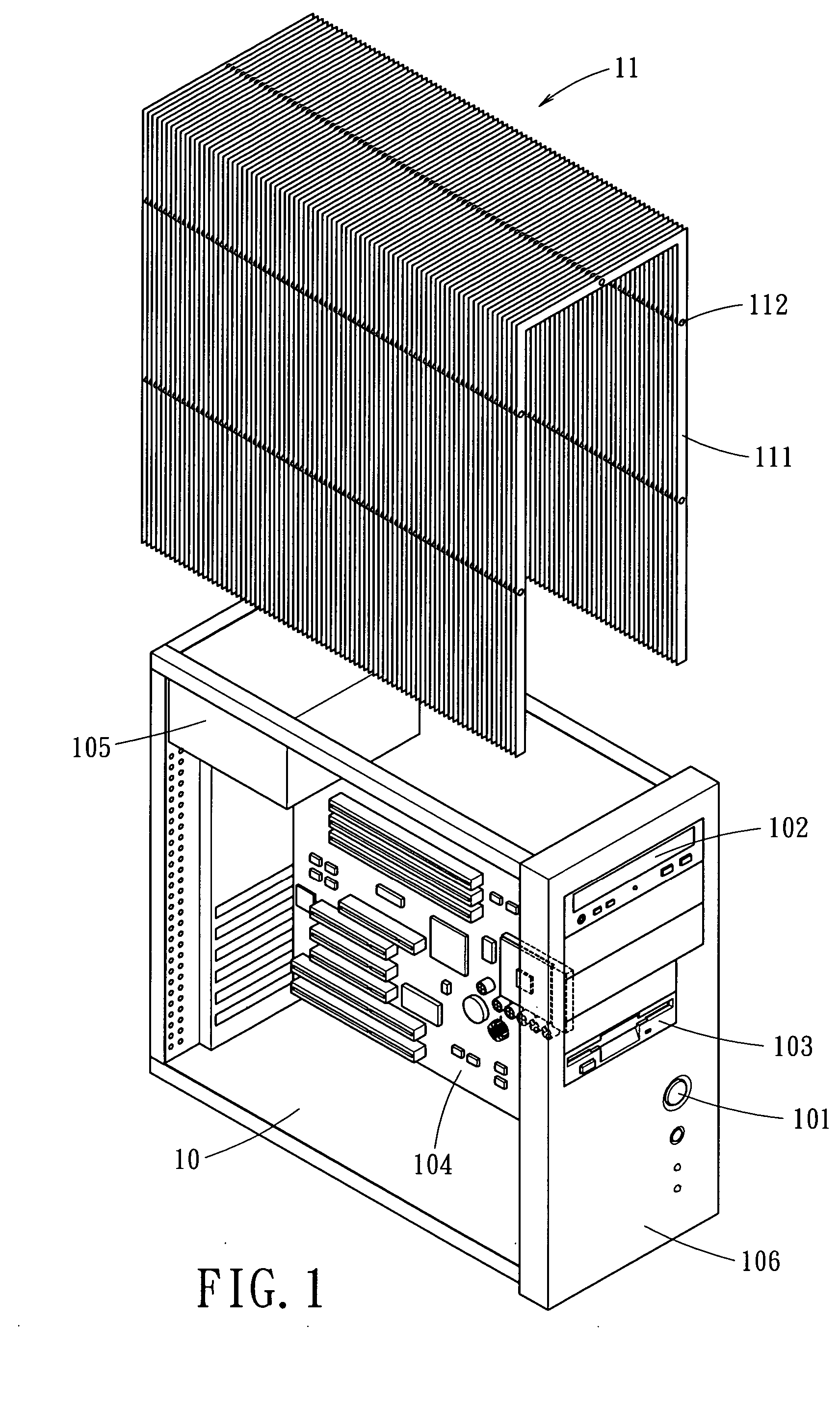
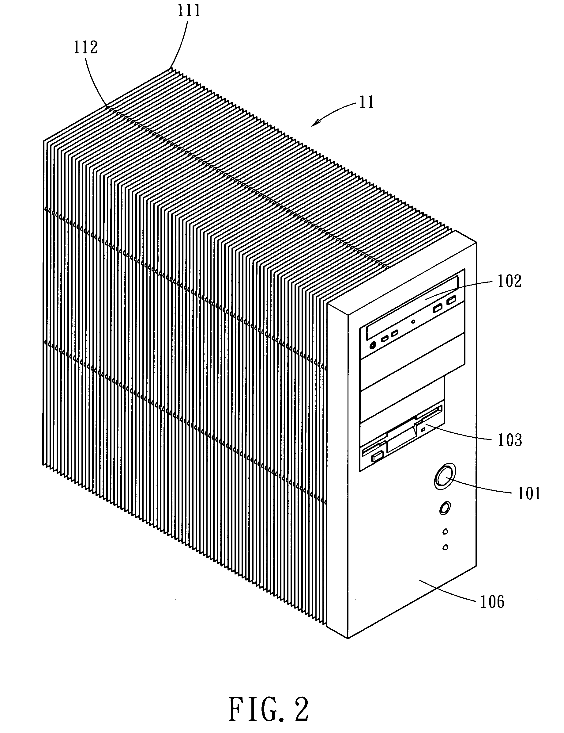
[0024] Referring to FIGS. 3 and 4, the exploded view and the perspective view of an integrated heat dissipating enclosure for an electronic product are shown. The cooling cover 11 includes a top heat sink panel 30, and a plurality of laterally extending fins 111 aligned with each other are arranged from two opposing elongate sides of the top heat sink panel 30. Therefore, an inverse U-shape space is formed allowing the frame 10 and the electronic product enclosed thereby to slide through. Similarly, thermal conductive pipes 112 penetrating through the fins 111 are used to integrate the fins 111 and the top heat sink panel 30. In this embodiment, the thermal conductive pipes 112 extend longitudinally through the fins 111 extending from each elongate side of the top heat sink panel 30. The integrated cooling cover 11 is then mounted to the frame 10 to form the integrated enclosure of the electronic product.

[0025]FIG. 5 shows a perspective view of a third embodiment of the present inve...

fourth embodiment

[0027]FIGS. 7 and 8 show the present invention. In this embodiment, an external cover 50 may be included to cover the cooling cover 11. The external cover 50 includes a plurality of elongate openings 501 to be aligned with spaces between the fins 111. Therefore, the protection of the internal devices of the electronic product can be reinforced, while the air circulation is maintained. In addition, by the protection of the external cover 50, the fins 111 are prevented from being deformed by external force or impact, particularly during transportation.

[0028] The external cover 50 may be made by using power metallurgy or bubble aluminum material to form a porous structure, so as to provide fine venting channels for air circulation.

[0029] The integrated heat dissipating enclosure for electronic products has at least the following advantages.

[0030] 1. Through the spaces between the fins 111 of the cooling cover 11, the internal of the electronic product is in communication with the ext...


PUM


Abstract

An integrated heat dissipating enclosure to provide heat dissipation for computer, power supply or other electronic products such as an integrated circuit on a motherboard, a central processing unit, or a chip on a video adapter. The enclosure has a frame and a cooling cover. The frame is used to carry various internal components or peripherals of a computer. The cooling cover has a plurality of fins spaced from each other by a space. The fins are connected together by a thermal conductive pipe to form an integrated heat dissipating enclosure.

Description

BACKGROUND OF THE INVENTION [0001] The present invention relates generally to an integrated heat dissipation enclosure for electronic products and, more particularly, to a cooler providing heat dissipation path for computer, power supply, or other heat generating devices such as an integrated circuit (IC) on a motherboard, a central processing unit (CPU), or a chip on a video adapter. [0002] The highly developed science and technology has continuously increased the execution speed of a chip. The higher execution speed of the chip consequently generates more heat, and increases the temperature of the chip. To effectively dissipate heat generated by the chip devices in an enclosure, so as to maintain the operation temperature of the heat generating devices therein, various kinds of heat dissipation structures have been developed. [0003] The conventional heat dissipation structure uses large area heat sink and heat dissipating fins attached to surfaces of heat generating devices, such ...

Claims


Application Information

Patent Timeline
IPC IPC(8): G06F1/18G06F1/20H05K5/00H05K7/20
CPCG06F1/181H05K7/20418G06F1/20
Inventor MENG-CHENG, HUANGMING-YANG, LIN
Owner CHAUN CHOUNG TECH
Why Eureka
Try Eureka