Chemical waste gas purification device and purification method

An exhaust gas purification device and exhaust gas purification technology are applied in the direction of chemical instruments and methods, separation methods, and separation of dispersed particles, which can solve problems such as air pollution, secondary pollution, and limited treatment effect, so as to increase the contact area and avoid pollution. Air, to achieve the effect of adsorption effect

Inactive Publication Date: 2015-10-21
CHANGZHOU HANGBIAO PRECISION MACHINERY CO LTD
View PDF8 Cites 3 Cited by
  • Summary
  • Abstract
  • Description
  • Claims
  • Application Information

AI Technical Summary

Problems solved by technology

The direct discharge of chemical tail gas will cause air pollution, and the existing waste gas conversion equipment has limited treatment effect, and at the same time, it is easy to cause secondary pollution

Method used


Image

  • Chemical waste gas purification device and purification method

Examples


Embodiment 1

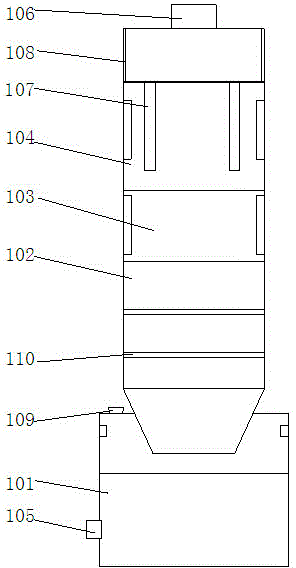
[0028] Such as figure 1 As shown, a chemical waste gas purification device includes a spray chamber 101, a drying chamber 102, a heating chamber 103 and an adsorption chamber 104 arranged sequentially from bottom to top;

[0029] The spray chamber 101 is provided with a water storage tank, and the lower part of one side of the spray chamber 101 is provided with a waste gas inlet 105, and the waste gas inlet 105 is provided with a high-pressure pump, and the inner wall of the spray chamber 10) There is a spray pump on it;

[0030] The drying chamber 102 is provided with a desiccant, and the drying chamber 102 is provided with at least two isolation boards 110, and the isolation boards 110 divide the drying chamber 102 into at least three chambers. A desiccant is provided in the room, and the isolation plate 110 is a double-layer thin plate provided with through holes;

[0031] The inner wall of the heating chamber 103 is provided with electric heaters, and the electric heater...

Embodiment 2

[0038] A method for purifying chemical waste gas, comprising the following steps:

[0039] S1: Acidify the waste gas, pass the waste gas into the spray chamber 101 with acid solution, make the aqueous solution in the spray chamber absorb the solid particles in the waste gas, and absorb the nitrogen oxides in the waste gas through the acid solution, Start the induced draft fan to suck the air in the adsorption chamber 104, so that negative pressure appears in the adsorption chamber;

[0040] S2: The exhaust gas processed in step S1 is passed into the drying chamber 102, and the moisture in the exhaust gas is absorbed by at least three layers of desiccant, and the dried exhaust gas enters the heating chamber 103 after passing through the air heater, and is heated by the electric heating in the heating chamber 103 The device heats the exhaust gas at high temperature to decompose the hydrocarbons and methane in the exhaust gas, and passes the decomposed gas into the adsorption cha...


PUM


Abstract

The invention discloses a chemical waste gas purification device, which comprises a spraying bin, a drying bin, a heating bin and an adsorbing bin in sequence from bottom to top, wherein a water storage tank is arranged in the spraying bin; a waste gas inlet is formed in the lower part of one side of the spraying bin; a high pressure pump is arranged above the waste gas inlet; a spraying pump is arranged on the inner wall of the spraying bin; a drying agent is arranged in the drying bin; partitioning plates are arranged in the drying bin; drying agents are respectively arranged in the bins; the partitioning plates are double layer thin sheets provided with through holes; electric heaters are arranged on the inner wall of the heating bin; two isolating mesh sieves are arranged in the absorbing bin; photocatalysts are arranged on the outer surfaces of the isolating mesh sieves; infrared lamps are arranged on the inner wall of the absorbing bin; an activated carbon absorption layer is arranged on the inner wall of the absorbing bin above the isolating mesh sieves; a waste gas outlet is formed above the absorbing bin. By adopting the chemical waste gas purification device and a purification method disclosed by the invention, treatment of particulate matters and gaseous compounds in chemical waste gas is realized, secondary pollution is reduced, and treatment efficiency is improved.

Description

technical field [0001] The invention relates to a chemical waste gas purification device and a purification method. Background technique [0002] Chemical waste gas refers to the poisonous and harmful gas discharged from chemical plants in chemical production. Chemical waste gas often contains many types of pollutants, complex physical and chemical properties, and different toxicity, which seriously pollutes the environment and affects human health. The composition of chemical waste gas produced by different chemical production industries varies greatly. For example, the waste gas produced by the chlor-alkali industry mainly contains chlorine, hydrogen chloride, vinyl chloride, mercury, acetylene, etc., and the waste gas produced by the nitrogen fertilizer industry mainly contains nitrogen oxides, urea dust, carbon monoxide, ammonia, sulfur dioxide, methane, etc. The direct discharge of chemical tail gas will cause air pollution, and the existing waste gas conversion equip...

Claims


Application Information

Patent Timeline
Patent Type & Authority Applications(China)
IPC IPC(8): B01D53/75B01D53/56B01D53/72B01D53/44B01D53/58B01D47/06
Inventor 严志林
Owner CHANGZHOU HANGBIAO PRECISION MACHINERY CO LTD
Why Eureka
Try Eureka