Motor driving apparatus for use in a diswasher

a technology for driving apparatus and diswasher, which is applied in the direction of motor/generator/converter stopper, electronic commutator, dynamo-electric converter control, etc., can solve the problems of increasing the thickness and the price of the motor, increasing the noise of the motor, and deteriorating the reliability, so as to improve the detection efficiency and reduce the size of the dc component. , the effect of small siz

Inactive Publication Date: 2005-06-16
PANASONIC CORP
View PDF15 Cites 18 Cited by
  • Summary
  • Abstract
  • Description
  • Claims
  • Application Information

AI Technical Summary

Benefits of technology

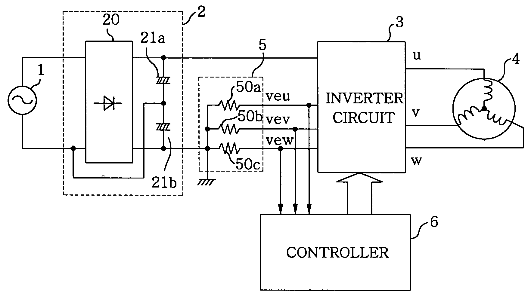
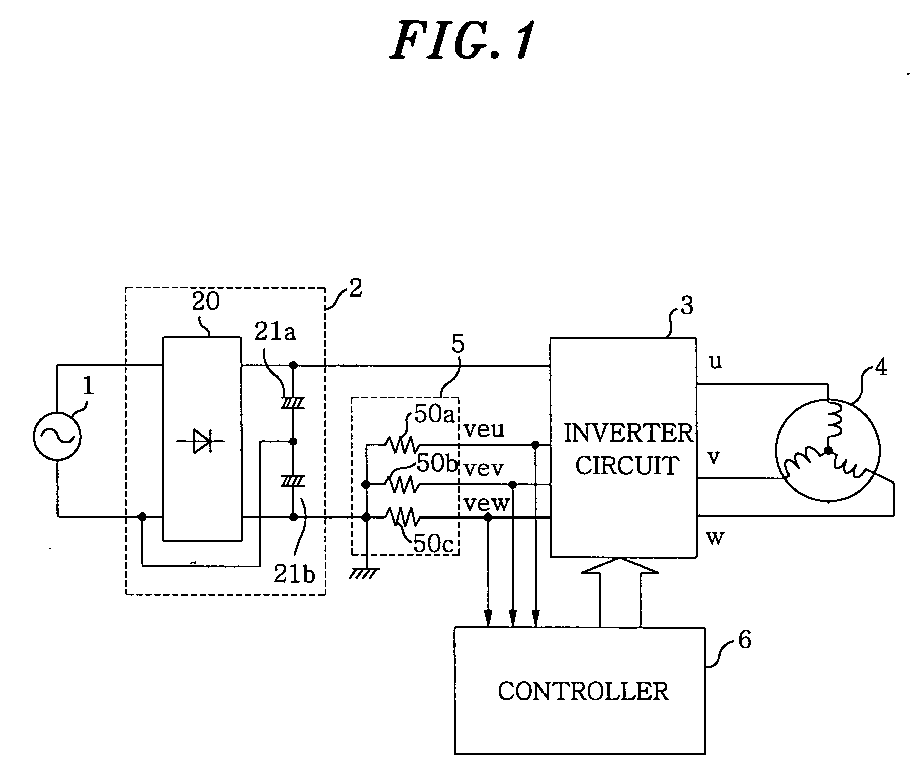
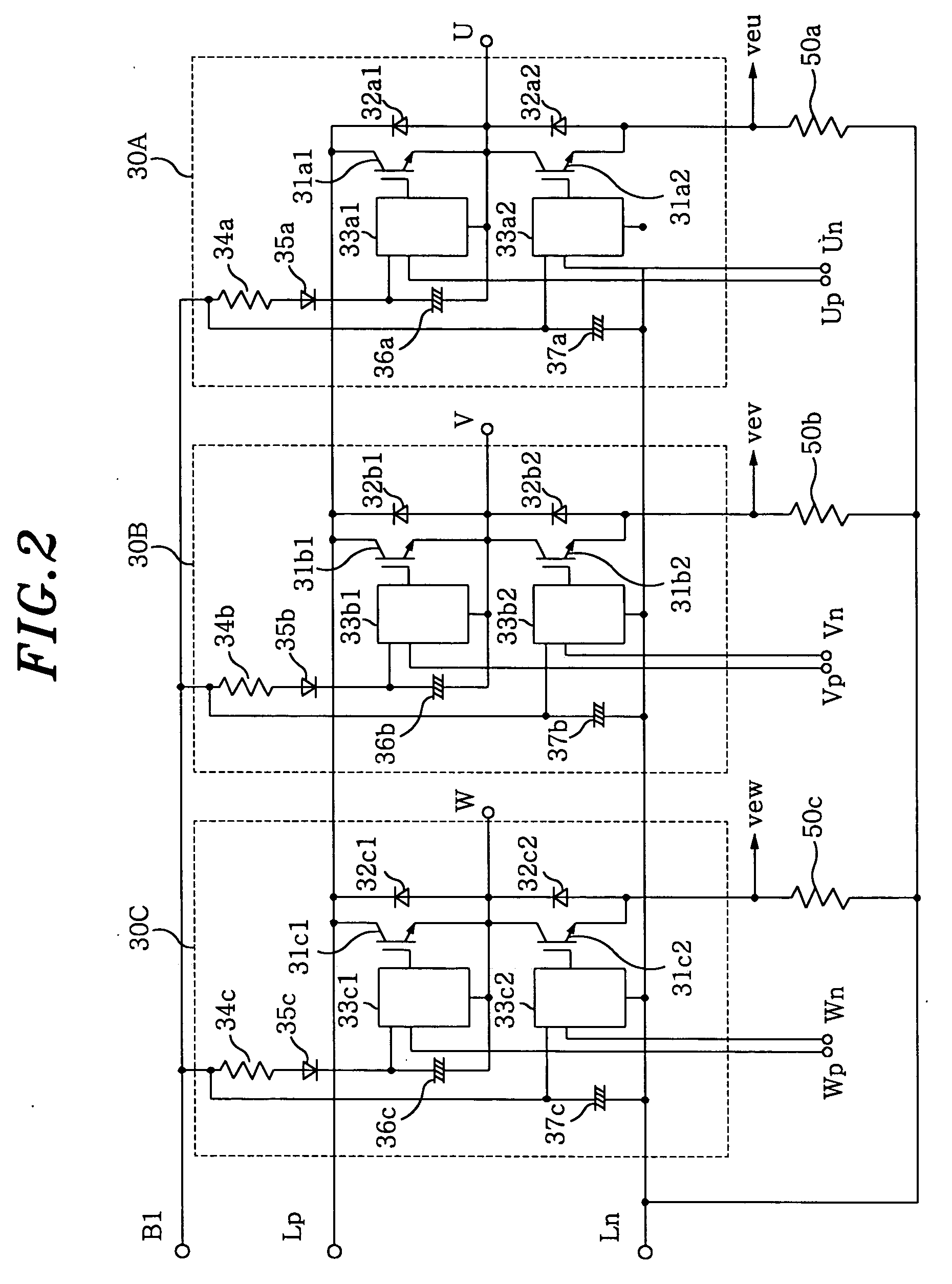
[0007] In the above configuration, the inverter circuit can be configured as a three phase full-bridge inverter circuit including six transistors and six diodes, and the current detector can include shunt resistors respectively connected to negative potential terminals of lower arm transistors of the three phase full-bridge inverter circuit, wherein the output current of the inverter circuit can be detected by detecting a current flowing through the shunt resistors. Therefore, since it becomes easier to detect a DC component and to configure the current detector by using the shunt resistors of low price, the current detector can be designed to have a small size and a low-price sensorless motor driving apparatus can be obtained.
[0008] In the above configuration, the motor may be a position-sensorless brushless DC motor having a planar shape. Therefore, the motor can be reduced in its size and can be configured to have a planar shape because it does not incorporate a position sensor therein. As a result, installation area for the motor in a bottom portion of a washer tub can be reduced, which in turn increases the volume of the portion in the washer tub for accommodating dishware. Thus, a large-capacity for dishwasher can be realized.
[0009] In the above configuration, the output current of the inverter circuit and an induced voltage of the motor may be controlled to have a substantially identical phase by way of controlling the phase between the output voltage and the output current of the inverter circuit or the reactive current to have the predetermined value. By setting the phase of the induced voltage and the phase of the motor current to be substantially identical, the motor current can be reduced, thereby enabling operation of maximum efficiency. Furthermore, since a rise in the temperature of the motor can be reduced, the size and thickness of the motor can be reduced. As a result, the installation area for the motor can be further reduced such that the volume of the portion in the washer tub for accommodating dishware can be increased, while realizing a large-capacity compact dishwasher at a low price.
[0010] In the above configuration, the output current of the inverter circuit may be controlled to lead the induced voltage of the motor by way of controlling the phase difference between the output voltage and the output current of the inverter circuit or the reactive current to have the predetermined value. By this configuration, the control can be stabilized even in case the phase of current is changed due to a variation in a load on the motor because the phase of the current does not lag with respect to that of the induced voltage to thereby prevent a reduction of a torque and a stop of the motor. Therefore, stable operation of the motor can be achieved even when there occurs a sudden change in the load thereon, such as an inflow of air into a pump, and, at the same time, a high-speed operation can be realized by a weak field control even for a multi-polar motor.
[0011] In the above configuration, the phase difference between the output voltage and the output current of the inverter circuit or the reactive current may be controlled to have the predetermined value by way of detecting the output current of the inverter circuit by means of the current detector in synchronous with a switching period for the PWM control of the inverter circuit and comparing a value of the output current detected by the current detector with a value of an output current that is calculated and set in synchronous with the switching period. Thus, detection of the phase of the motor current, the reactive current or an absolute value of current becomes feasible by using a carrier frequency higher than a motor driving frequency, and it becomes possible to cope with the change in the load of the motor by reducing a time period required to respond to a motor control. As a result, stable operation can be achieved even when there occurs a sudden change of the load on the motor, such as an inflow of air.
[0012] In the above configuration, a wash pump operation or a drain pump operation may be enabled by allowing the motor to make forward or backward rotations, and an inflow of air in the wash pump or the drain pump can be detected if the output current of the inverter circuit falls below a preset value while driving the wash pump or the drain pump by controlling the motor to rotate at a set rotation speed. In order to prevent increase of noise when the inflow of air is detected, the rotation speed of the motor may be reduced or the quantity of wash water may be increased. Further, during a drain operation, by temporarily stopping the operation of the drain pump until wash water is collected in a lower portion of the washer tub and resuming the operation of the drain pump, the operating time can be reduced, thereby lowering the generation of noise.

Problems solved by technology

As a result, there has been a problem that waveform distortion of a motor current and a noise of the motor are increased.
On the other hand, if a motor is driven not on a sensorless driving method but on the basis of a position sensor signal, a position sensor has to be installed within the motor, which would result in an increase in both the thickness and the price of the motor, while deteriorating the reliability thereof.

Method used


Image

  • Motor driving apparatus for use in a diswasher
  • Motor driving apparatus for use in a diswasher
  • Motor driving apparatus for use in a diswasher

Examples


second preferred embodiment

[0057]FIG. 8 is a flow chart of a motor control program that describes the operation of the motor driving apparatus for use in the dishwasher in accordance with the present invention.

[0058] A motor driving program is started in step 100, and setting of various parameters, e.g., a driving frequency, a ratio of V / f, and a reactive current is performed in step 101. Then, it is determined whether a motor's operation is a start-up operation in step 102, and, if so, a start-up control subroutine is executed in step 103.

[0059] The start-up control subroutine 103 is for linearly increasing driving frequency f from 0 to set frequency fs. Depending on driving frequency f, a V / f control and a setting value for reactive current Irs are varied. As for a pump load, the load torque is changed by the square of the rotation speed. Thus, a stable driving control can be performed by obtaining torque current Iq corresponding to a rotation speed, calculating I sin φ and performing a driving control wi...


PUM


Abstract

An apparatus for driving a motor of a dishwasher includes an AC power source, a rectification circuit for converting an AC power from the AC power source to a DC power, an inverter circuit for converting the DC power from the rectification circuit to an AC power, a motor driven by the inverter circuit to drive a wash pump and/or a drain pump, a current detector for detecting an output current of the inverter circuit, and a controller for performing a PWM (pulse width modulation) control of the inverter circuit based on an output signal of the current detector to thereby control the motor to rotate at a set rotation speed. A phase difference between an output voltage and the output current of the inverter circuit or a reactive current is controlled to have a predetermined value.

Description

FIELD OF THE INVENTION [0001] The present invention relates to a dishwasher for cleaning household dishware. BACKGROUND OF THE INVENTION [0002] Conventionally, with regard to a motor driving apparatus for use in a dishwasher, it is required to reduce the size of a pump motor by employing a sensorless brushless motor driven by an inverter (see, for example, Japanese Patent Laid-open Application No. 2003-190070). [0003] In the above configuration, however, since a motor induced voltage should be obtained for the detection of a position of a rotor, a motor driving method such as a rectangular wave driving may be employed. As a result, there has been a problem that waveform distortion of a motor current and a noise of the motor are increased. [0004] On the other hand, if a motor is driven not on a sensorless driving method but on the basis of a position sensor signal, a position sensor has to be installed within the motor, which would result in an increase in both the thickness and the ...

Claims


Application Information

Patent Timeline
Patent Type & Authority Applications(United States)
IPC IPC(8): A47L15/42A47L15/46H02P6/06H02P6/08H02P6/15H02P6/18H02P6/182H02P6/28H02P21/00H02P21/05H02P21/22H02P21/34H02P23/04H02P27/04H02P27/08
CPCA47L15/0052H02P6/205H02P6/08A47L15/4225H02P6/21A47L15/42A47L15/46H02P7/34
Inventor KIUCHI, MITSUYUKISUZUKI, MASAHIRONAKATA, HIDEKIYOSHIOKA, KANEHARU
Owner PANASONIC CORP
Why Eureka
Try Eureka