Non-reciprocal circuit device having small absolute value of temperature coefficient of out-of-band attenuation and small absolute value of temperature coefficient of maximum- isolation frequency

a non-reciprocal circuit and temperature coefficient technology, applied in the field of non-reciprocal circuit devices and communication devices, can solve problems such as noise generation from the antenna of a communication device, and achieve the effects of stable performance, reduced fluctuations in the characteristic of the communication device in the operating environment, and high out-of-band attenuation

Inactive Publication Date: 2005-06-16
ALPS ALPINE CO LTD
View PDF0 Cites 16 Cited by
  • Summary
  • Abstract
  • Description
  • Claims
  • Application Information

AI Technical Summary

Benefits of technology

[0032] In a communication device including the non-reciprocal circuit device described above, the out-of-band attenuation is high, and the absolute values of a temperature coefficient of out-of-band attenuation and a temperature coefficient of maximum-isolation frequency are small. Thus, fluctuations in the characteristic of the communication device in the operating environment can be reduced, thereby achieving a stable performance. Moreover, the non-reciprocal circuit device has high out-of-band attenuation, so that the antenna of the communication device does not produce noise.
[0033] The non-reciprocal circ...

Problems solved by technology

This causes generation of noise fr...

Method used


Image

  • Non-reciprocal circuit device having small absolute value of temperature coefficient of out-of-band attenuation and small absolute value of temperature coefficient of maximum- isolation frequency
  • Non-reciprocal circuit device having small absolute value of temperature coefficient of out-of-band attenuation and small absolute value of temperature coefficient of maximum- isolation frequency
  • Non-reciprocal circuit device having small absolute value of temperature coefficient of out-of-band attenuation and small absolute value of temperature coefficient of maximum- isolation frequency

Examples


experiment 1

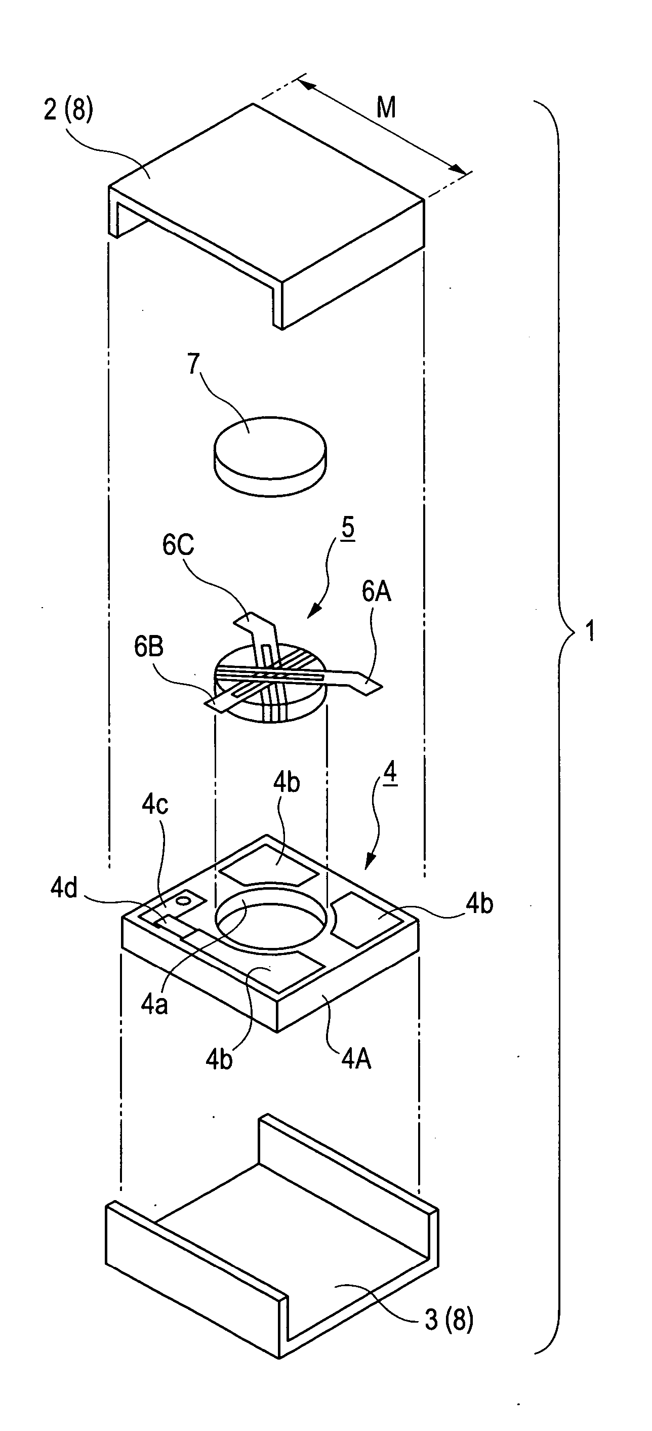
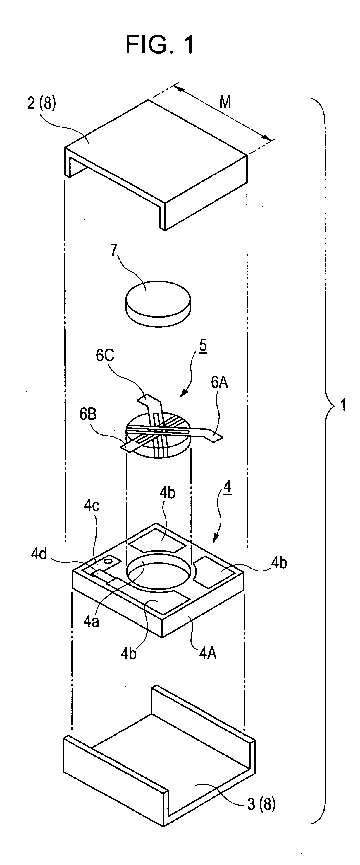
[0079] Isolators of 3.2 mm per side as shown in FIG. 1 were prepared in Examples 1 to 3, and Comparative Examples 1 to 6 to examine fluctuations in center frequencies of isolation values and fluctuations in out-of-band attenuation. The temperature coefficients (α) of 4πMs of magnetic disks used in the isolators were also examined.

example 1

[0080] A magnetic disk composed of YIG ferrite and having an approximately-hexagonal shape, as viewed from the top, of about 1.5 mm long by about 2.47 mm wide by 0.35 mm thick was used as a magnetic disk 5. An SmCo-based magnet composed of Sm2(CoFeCu)1, was used as a biasing magnet. BHmax, the residual magnetization Br, the coercive force bHc, and the temperature coefficient of residual magnetization in the range of 25° C. to 85° C. of the SmCo-based magnet were respectively 191 kJ / m3, 1.05 T, 636 kA / m, and −0.04% / ° C. An isolator of Example 1 as shown in FIG. 1 was prepared with these magnetic disk and magnet. The composition of the magnetic disk is shown in Table I. A matching capacitor connected to a central conductor at the input side was composed of a dielectric material of barium titanate and had a capacitance C1 of 12.3 pF, a matching capacitor connected to a central conductor at the output side had a capacitance C2 of 12.2 pF, and a matching capacitor connected to a terminat...

example 2

[0081] An isolator of Example 2 was prepared as in Example 1 except that the composition of the magnetic disk 5 was changed. The composition of the magnetic disk is shown in Table I.


PUM


Abstract

A non-reciprocal circuit device includes a magnetic disk; a plurality of central conductors intersecting each other on a surface of the magnetic disk; a plurality of matching capacitors connected to the respective central conductors; and an SmCO-based or AlNiCo-based magnet that is stacked on the magnetic disk, the SmCO-based or AlNiCo-based magnet applying a bias magnetic field to the magnetic disk. The magnetic disk is composed of garnet ferrite represented by any one of the following Formulae (1) to (3):
Y3-xGdxFet-2y-zCoySiyAlzO12  (1)
Y3-x-uGdxCauFet-2y-u-zCoySiyDuAlzO12  (2)
Y3-xGdxFet-2y-v-zCoySiyInvAlzO12  (3)

Description

BACKGROUND OF THE INVENTION [0001] 1. Field of the Invention [0002] The present invention relates to non-reciprocal circuit devices and communication devices, which are used in a high-frequency band such as a microwave band, and in particular, relates to a non-reciprocal circuit device having a small absolute value of a temperature coefficient of out-of-band attenuation and a small absolute value of a temperature coefficient of maximum-isolation frequency. [0003] 2. Description of the Related Art [0004] An isolator, a type of lumped-constant non-reciprocal circuit device, is a high-frequency component that transmits signals in the transmission direction without loss and prevents signals from passing through in the reverse direction, and is used in transmitters of mobile communication devices such as mobile phones. [0005] An isolator includes a magnetic yoke that accommodates a magnetic assembly having a magnetic disk composed of ferrite and the like assembled with a plurality of cen...

Claims


Application Information

Patent Timeline
IPC IPC(8): C04B35/40H01P1/36H01P1/383H01P1/387
CPCH01P1/387
Inventor TAKAHASHI, TOSHIOONISHI, HITOSHI
Owner ALPS ALPINE CO LTD
Why Eureka
Try Eureka