
High bandwidth data transport system

a data transport system and high-bandwidth technology, applied in the direction of transmission/receiving by adding signal to wave, pulse technique, instruments, etc., can solve the problems of insufficient real-time broadband availability, limited amount of services, and large text-based internet content, so as to increase the bandwidth of guided line networks, short duty cycle, and low cost

Inactive Publication Date: 2005-06-16
LIGHTWAVES SYST
View PDF37 Cites 55 Cited by
  • Summary
  • Abstract
  • Description
  • Claims
  • Application Information

AI Technical Summary

Benefits of technology

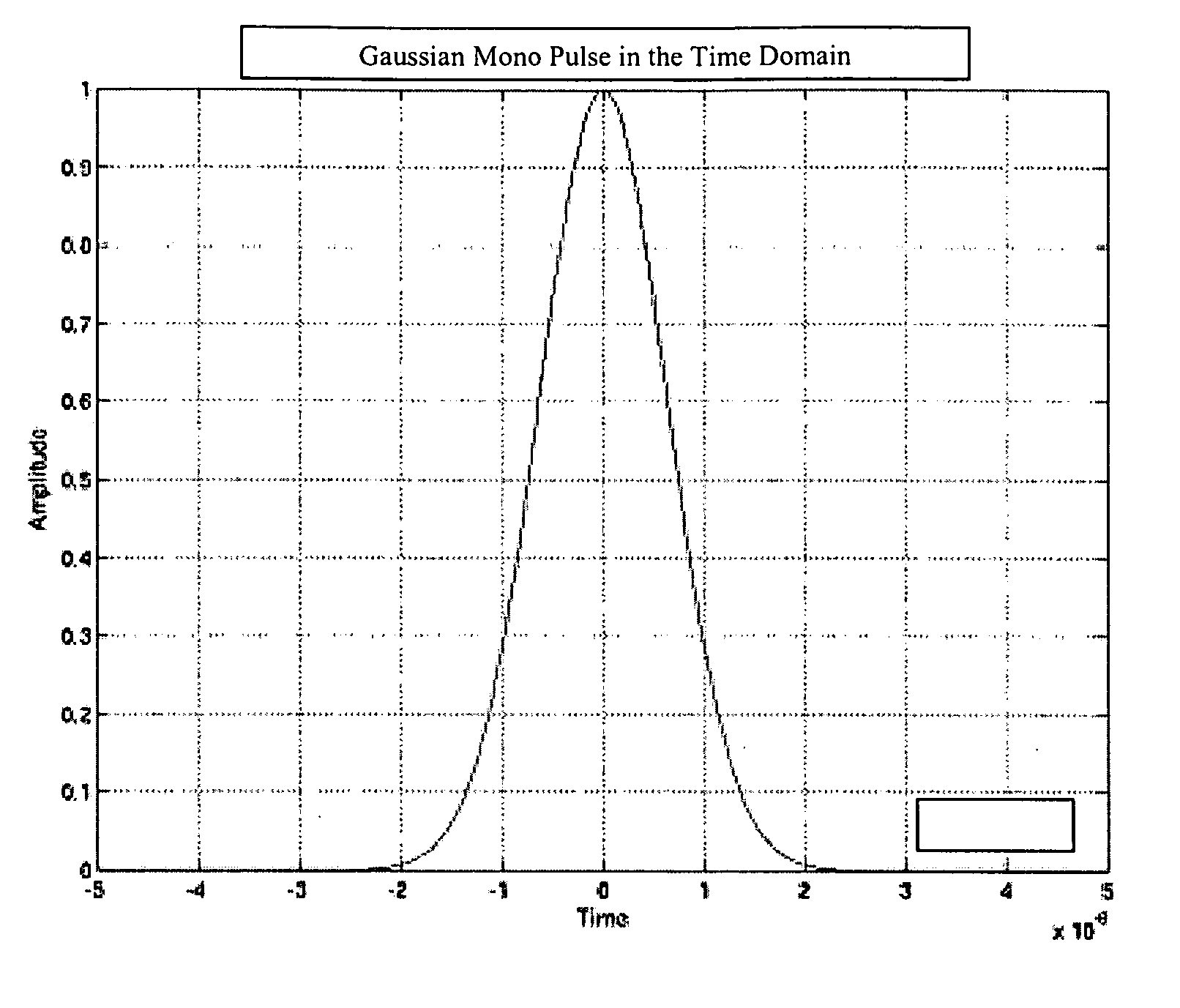
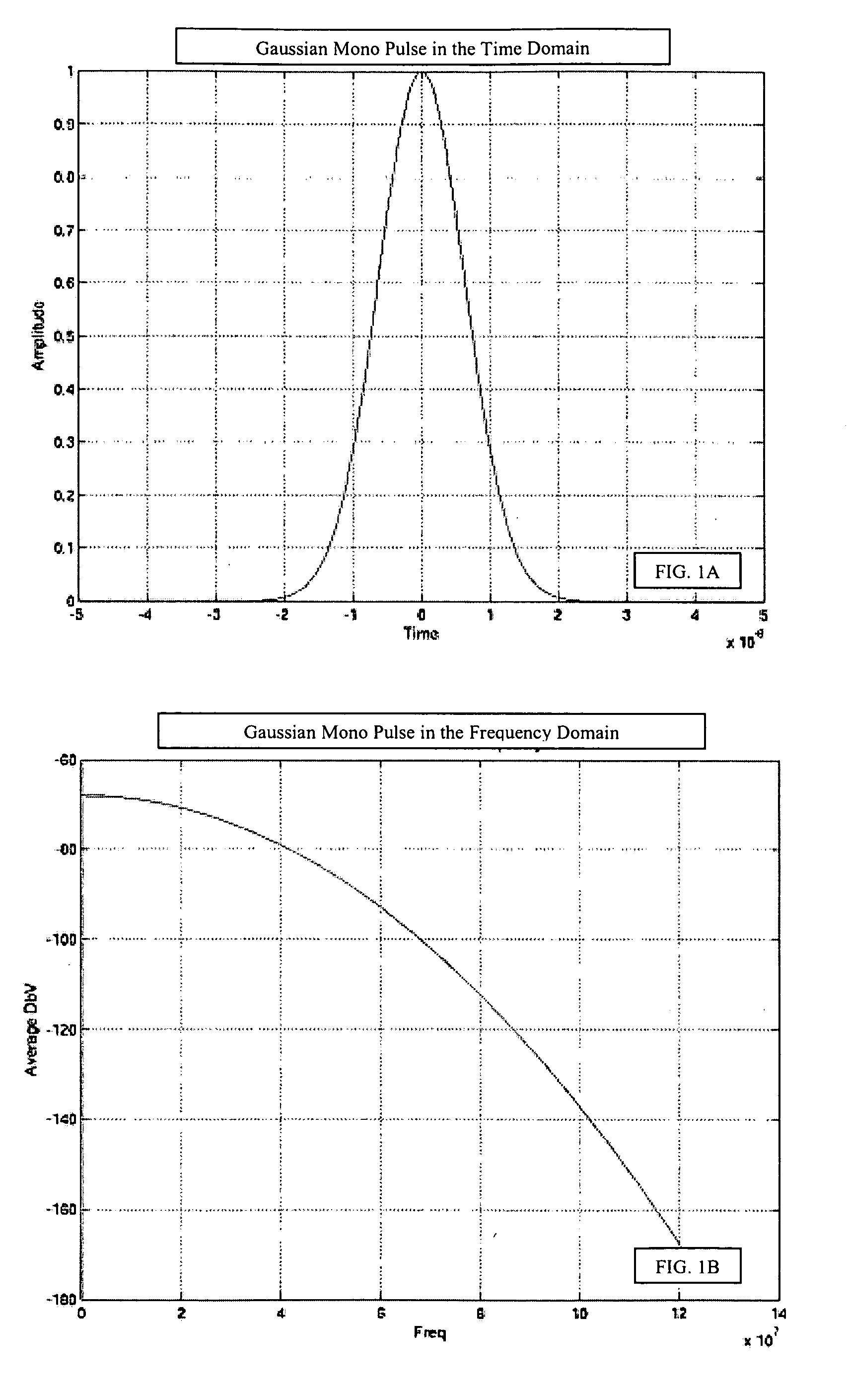
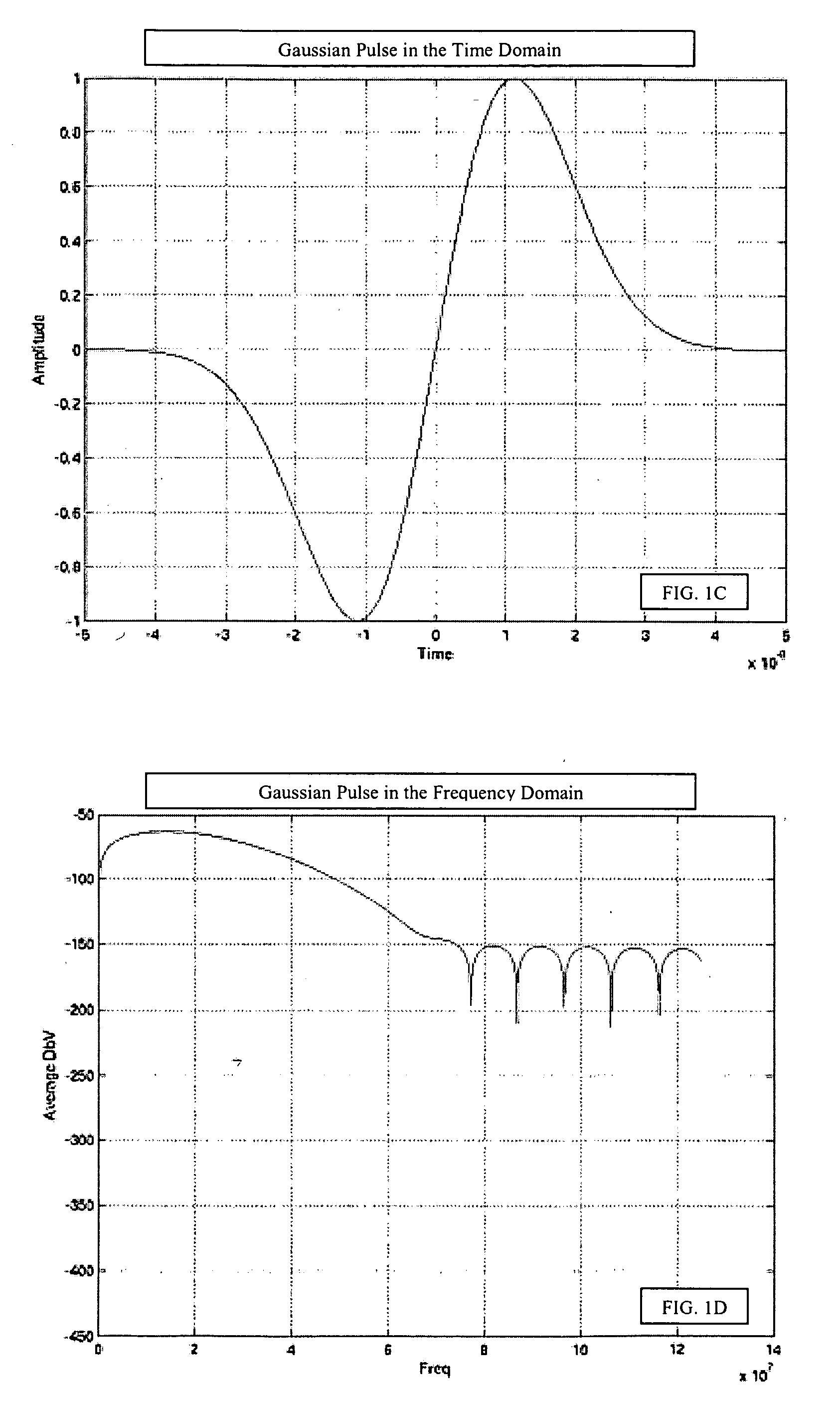
[0152] The present invention is a system, method and apparatus for increasing the bandwidth of guided line networks using ultra wideband pulse transmissions. The ultra wideband pulses of the present invention are short, low duty cycle. These ultra wideband pulses enable a high data rate over increased distance...

Problems solved by technology

The rise of the Internet and networks has provided ubiquitous connectivity for businesses and consumers alike, but are being constrained by the lack of true broadband availability.
Initially, Internet content was largely text-based and provided limited amount of services.
However, the Internet has grown to provide more bandwidth intensive content filled with pictures, graphics, and video clips.
Even though there is currently a glut of high-speed fiber optic backbone capacity, with an overall utilization rate of only 3% to 5%, the access network, or what is commonly referred to as the “first mile” or “last mile”, simply cannot keep pace with the need and desire for higher speed access to larger amounts of digital information.
However, the major impediment to the delivery of high-bandwidth Internet content and services is the transmission constraints from the major Internet pipes to the customer's home or business, also known as the “last mile.”
Even though fiber optic transmission lines can provide a significant amount of bandwidth, laying fiber to the home or business has proven to be too costly.
Wireless is also an expensive access network solution, and the total available bandwidth is limited and shared.
Currently, cable and telephone twisted pair access networks are limited by the physics of continuously oscillating radio frequency technology.

Method used


Image

  • High bandwidth data transport system
  • High bandwidth data transport system
  • High bandwidth data transport system

Examples


Embodiment Construction

[0180] The present invention is a departure from existing impulse radio techniques used for wireless transmission of data. In order to introduce the reader to the present invention, the following technology overview is provided as a precursor to the specific embodiments of the present invention. The intention of this overview is to assist the reader with the understanding of the present invention, and should not be used to limit the scope of the present invention.

[0181] One aspect of the present invention refers to a radio frequency system designed for use in high attenuation and capacitance environments which are commonly found on metallic guided-line conductors, such as but not limited to, telephone twisted pair, coaxial cable, Category 5 cable, power lines, other conductive mediums, such as but not limited to, metallic car and truck bodies, ship and submarine hulls, decks and bulkheads, aircraft fuselages, structural steel, missile bodies, tank bodies, water pipes, etc. The term...


PUM


Abstract

The present invention provides for a methods, system, and apparatus relating to data transmission. One method of the present invention includes representing data using at least one ultra wideband pulse, sending the at least one ultra wideband pulse over an electrically conductive guided media, and recovering the data from the at least one ultra wideband pulse. The present invention can be used in conjunction with telephony applications, cable TV applications, power line applications, fiber optic applications, and data bus applications.

Description

CROSS-REFERENCE TO RELATED APPLICATIONS [0001] This application is a conversion of and claims priority to prior U.S. Provisional Patent Application, Ser. No. 60 / 512,367 entitled COUNTER PULSE HIGH BANDWIDTH DATA TRANSPORT SYSTEM filed on Oct. 17, 2003, which is herein incorporated by reference in its entirety. This application is a continuation-in-part of and claims priority to U.S. patent application, Ser. No. 10 / 427,039, entitled HIGH-BANDWIDTH DATA TRANSPORT SYSTEM, filed on Apr. 30, 2003, which was a conversion of 60 / 376,592 filed Apr. 30, 2002 and 60 / 441,358 filed Jun. 20, 2003, all of which are herein incorporated by reference in its entirety. This application is also a continuation-in-part and claims priority to Ser. No. 09 / 698,793 entitled METHOD OF TRANSMITTING DATA INCLUDING A STRUCTURED LINEAR DATABASE, filed on Oct. 27, 2000, which was a conversion of 60 / 162,094 filed Oct. 28, 1999, and 60 / 163,426 filed Nov. 3, 1999 and 60 / 220,749 filed Jul. 26, 2000, all of which are he...

Claims


Application Information

Patent Timeline
IPC IPC(8): G06F7/00H04M11/00
CPCH04B1/7163H04B1/7172H04B1/7176H04L25/0384H04L5/1469H04L25/4902H04L27/0004H04B2203/5416
Inventor KENNEDY, PHILIP T.MELICK, BRUCE D.SNYDER, DAVID M.BAYCH, LESLIE D.
Owner LIGHTWAVES SYST
Learn More