Converting energy from flowing fluids into electrical energy

a technology of electrical energy and flowing fluids, applied in the direction of fluid couplings, couplings, machines/engines, etc., can solve the problems of large and expensive pipes, complicated and expensive equipment, etc., and achieve the effect of inexpensive and effective electric power

Inactive Publication Date: 2005-06-23
NEWMAN EDWIN
View PDF9 Cites 11 Cited by
  • Summary
  • Abstract
  • Description
  • Claims
  • Application Information

AI Technical Summary

Benefits of technology

[0015] The second object is to provide inexpensive and effective electric power from wind and subsurface ocean currents.

Problems solved by technology

But to avoid large energy losses through the airpipe due to friction a large and expensive pipe is needed.
This involves complicated and expensive equipment.

Method used


Image

  • Converting energy from flowing fluids into electrical energy
  • Converting energy from flowing fluids into electrical energy
  • Converting energy from flowing fluids into electrical energy

Examples


first preferred embodiment

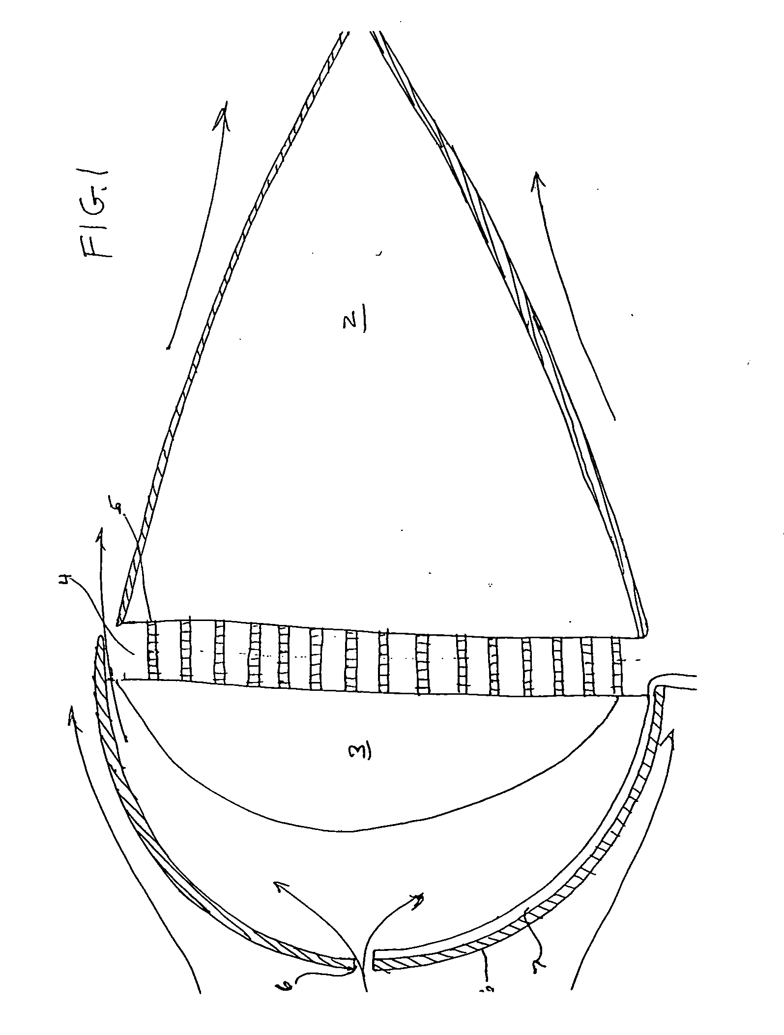
[0025] Turning to FIG. 1 there is shown a cut-away section of a hollow dome 1 fixed to a hollow cone 2 by intermittent spacers 5 making space 4. There is shown hole 6 and a tube 7 whose open end lies near hole 6. A second hollow dome 3 is affixed to hollow dome 1 at its rim.

[0026] In operation, as working fluid, which is wind, passes around the teardrop shape 1,2 this working fluid is pulled through hole 6 and out space 4 with dome 3 serving as a further guide to the working fluid.

[0027] In FIG. 3 we see the apparatus of FIG. 1 mounted on base 16, tube 15 and telescoped tube 14. Thrust bearings 19a,b allow the apparatus to be rotated according to wind direction by rudder 13.

[0028]FIG. 4 shows how varying pressure in tube 7 may be converted into electrical energy. Valve 36 is a three way valve admitting either reduced pressure from hole 6 or atmospheric pressure from tube 21 which is open to the atmosphere. Mounted on supports 19,20 are three shafts, 32,33,34. On shaft 32 are moun...

second preferred embodiment

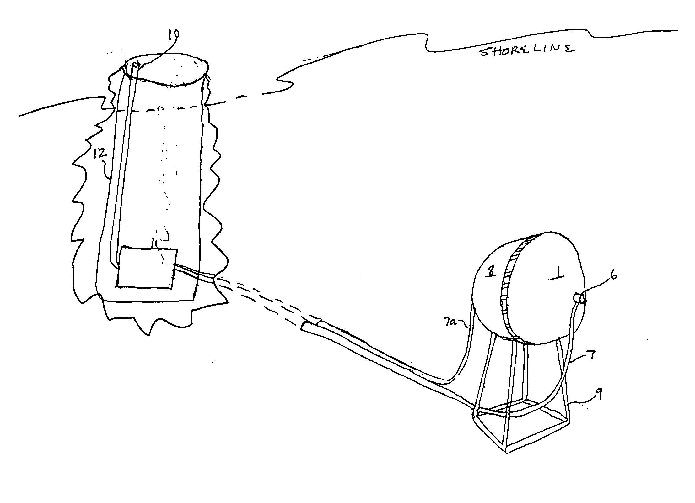
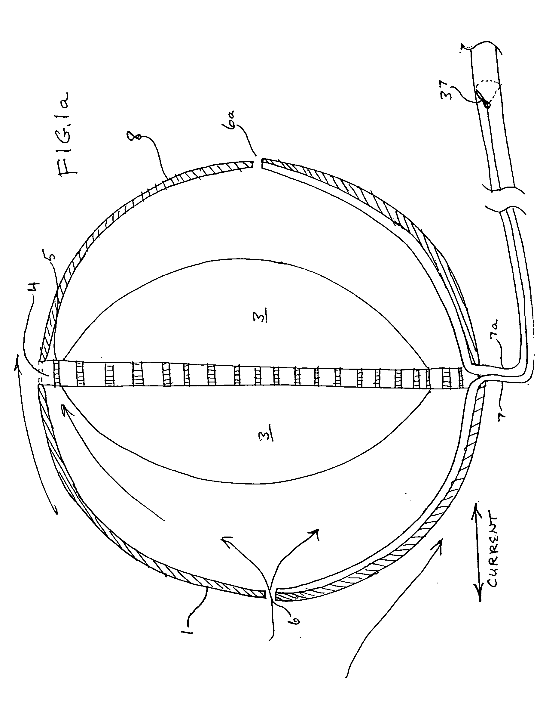
[0030] In FIG. 1a there is shown how to apply the apparatus of FIG. 1 to convert the energy of subsurface ocean energy to electrical energy ashore. Support 9 supports the apparatus of FIG. 1a on the bottom of the ocean so holes 6,6a are made to face an oncoming current which may change direction 180 degrees. Pressure energy in pipe 7 is correspondingly reduced at the end of pipe 7 at the bottom of excavation 12 when 3-way valve 36 is opened. Pipe 7a is led to near hole 6a for use when the current reverses direction. Valve 37 is made to alternately open and close pipes 7,7a according to the prevailing direction of the current.

[0031] In FIG. 5 we see an alternative way to convert varying pressure in tube 7 into electricity as the invention is applied to the conversion of the energy of subsurface ocean currents. Tube 7 is led into an onshore excavation 12 and is made to end horizontally as a Bourdon tube 22. Three way valve 36 is revolved and pressure from tube 21 alternates with the ...

third preferred embodiment

[0032] Turning to FIG. 6 we see a wheel and axle device as a disc 11 mounted on shaft 15. Tube 17 is located radially within disc 11 with openings near the rim. Tube 17 is bent at disc 11 axis and laid through the axis of shaft 15 which is operatedly connected to turbine 42, shaft 43 and generator 35. Rotateable seal 46 is mounted on tube 17 so only a portion of tube 17 revolves with disc 11.

[0033] In operation as disc 11, possibly a waterwheel, vehicle tire, or a gear is made to rotate then air is thrown out of tube 17 through openings 17,a-g. which each are of the same diameter as tube 17. These openings are near disc 11 rim. This is accomplished by inertia and a lifting force on the air in tube 17. The lowered pressure in tube 17 provides an energy sink to operate turbine 42 and electric generator 35.


PUM


Abstract

A new type of diverging nozzle is used to convert the energy of wind and subsurface ocean current into electrical energy. The nozzle is of either spherical or teardrop shape with a small hole in the surface facing the fluid stream. The fluid is made to exit through the surface where the widest diameter of the shape is. The fluid is drawn out by the Bernouilli Effect into the passing fluid stream. As the fluid is accelerated through the small hole the fluid in a tube whose first entrance is near the small hole has its pressure reduced. The tube's second entrance is an inlet tube to a Bourdon Tube. The flexing of the Bourdon tube is made to operate an electric generator through certain gearing. As long as there is a pressure difference between the fluid within the tube and the atmosphere then pressure within the Bourdon Tube can be alternated by valves so electric power output is maintained. Offshore, no moving parts are employed in the invention. The invention is also applied to recover energy needed to rotate a wheel, which may be a gear. Instead of a Bourdon tube a secondary turbine is used.

Description

[0001] Prior application Ser. No. 10 / 742,983 filed Dec. 23, 2003 abandoned. This application is a continuation-in-part.BACKGROUND OF THE INVENTION [0002] 1. Field of the Invention [0003] The present invention relates to the conversion of the pressure energy of flowing fluids into electrical energy. In particular the invention relates to the conversion of pressure energy from the wind, subsurface ocean currents into electrical energy and the recovery of some of the energy used to rotate shafts. [0004] 2. The Prior Art [0005] Wind and subsurface ocean currents are fluids possessing mechanical energy. The two relevant components of mechanical energy are pressure energy and kinetic energy. Up to now only some few efforts hve been made to convert the pressure energy of these fluids into electricity. Yet the pressure energy of these two fluids as they naturally occur is far greater than their kinetic energy. [0006] Hydroelectric turbine generators are a prime example of devices which conv...

Claims


Application Information

Patent Timeline
Patent Type & Authority Applications(United States)
IPC IPC(8): F16D31/02
CPCF03B17/00F03D5/00Y02E10/70Y02E10/20F03G7/04
Inventor NEWMAN, EDWIN
Owner NEWMAN EDWIN
Why Eureka
Try Eureka