Integrated solar energy roofing construction panel

a solar energy and roofing technology, applied in the direction of hybrid energy generation, pv power plants, lighting and heating apparatus, etc., can solve the problems of inability to heat the top surface of the photovoltaic device, minimize installation preparation, etc., to save installation costs and labor, reduce installation costs, and reduce the effect of installation cos

Inactive Publication Date: 2005-06-23
KONOLD ANNEMARIE HVISTENDAHL +1
View PDF20 Cites 176 Cited by
  • Summary
  • Abstract
  • Description
  • Claims
  • Application Information

AI Technical Summary

Benefits of technology

[0012] The invention is an improvement to an existing multi-function solar collector panel concept that performs a function for solar energy conversion into electrical current, a solar energy heating function for heating a working fluid and a heat radiator function to radiate heat, for melting snow or ice in cold climate applications or for other purposes, within a single enclosure. The improvement incorporates an embedment integrated with building construction material and solar collector panel embedment interface to save on installation costs and labor required installing a solar collector panel. Additional improvements provide for a lighter, more compact design by utilizing thinner, smaller cross-section component materials. Enhancements for fire protection and water runoff collection for non-potable usage are also provided. The incorporation of the embedment integrated with building materials and the solar panel with integrated embedment interface and the other enhancements provides a smaller, light weight solar collector panel with installation cost savings and functionality that previous inventions do not provide.

Problems solved by technology

These devices save on installation time and cost with minimal installation preparation; however, they are capable of only converting solar energy into electrical DC current and have no inherent capability to heat the photovoltaic device's top surface allowing for melting of snow or ice for applications in winter conditions or cold climates.
Therefore, there is an unmet need in the art for solar collecting devices that are light weight, integrate construction roofing materials within their design for direct installation using standard construction techniques, and convert solar energy to both thermal and electrical energy efficiently in colder climates by adding a function to radiate heat to both cool fluids and keep the solar collectors free of snow and ice.

Method used


Image

  • Integrated solar energy roofing construction panel
  • Integrated solar energy roofing construction panel
  • Integrated solar energy roofing construction panel

Examples


first embodiment

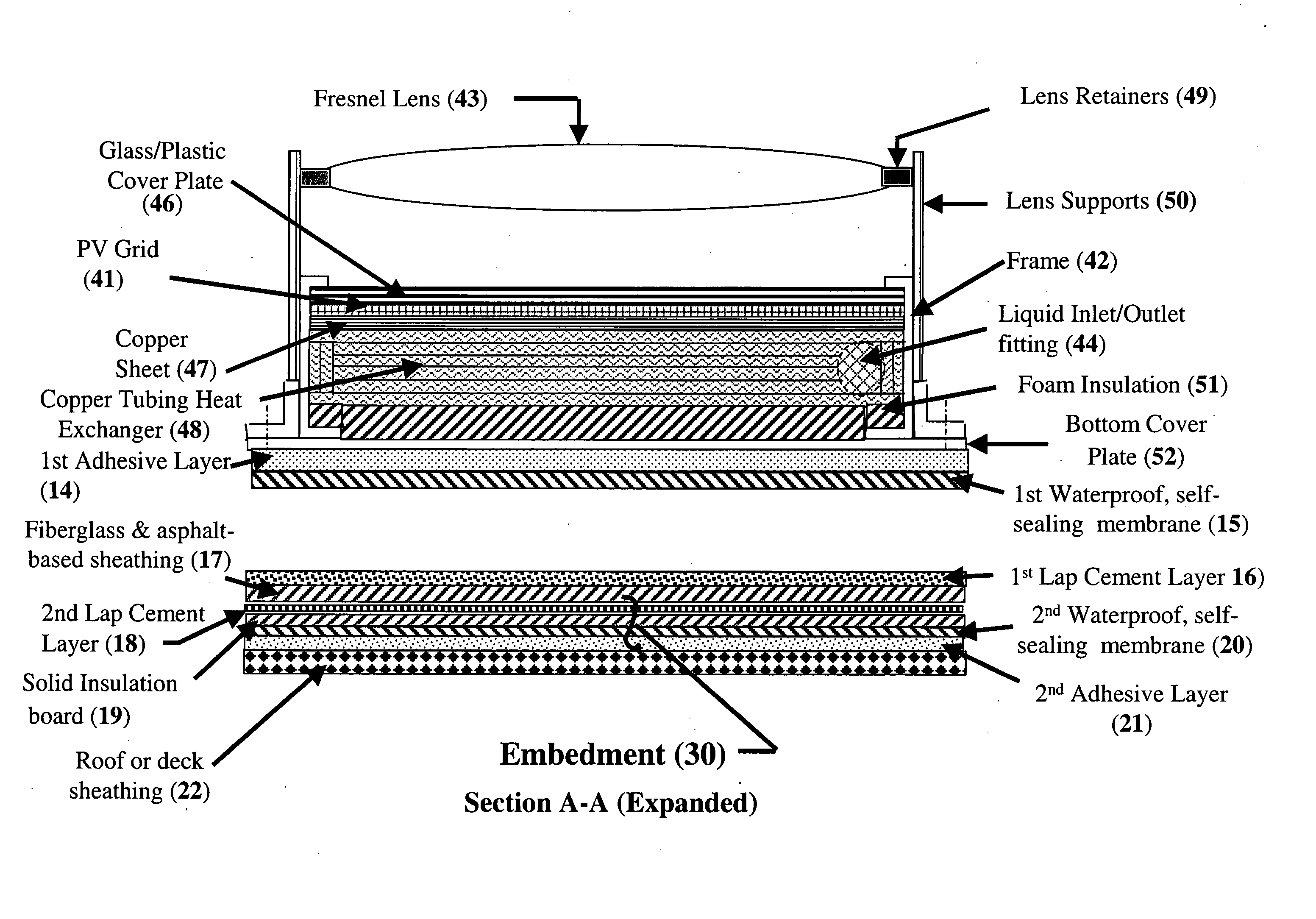
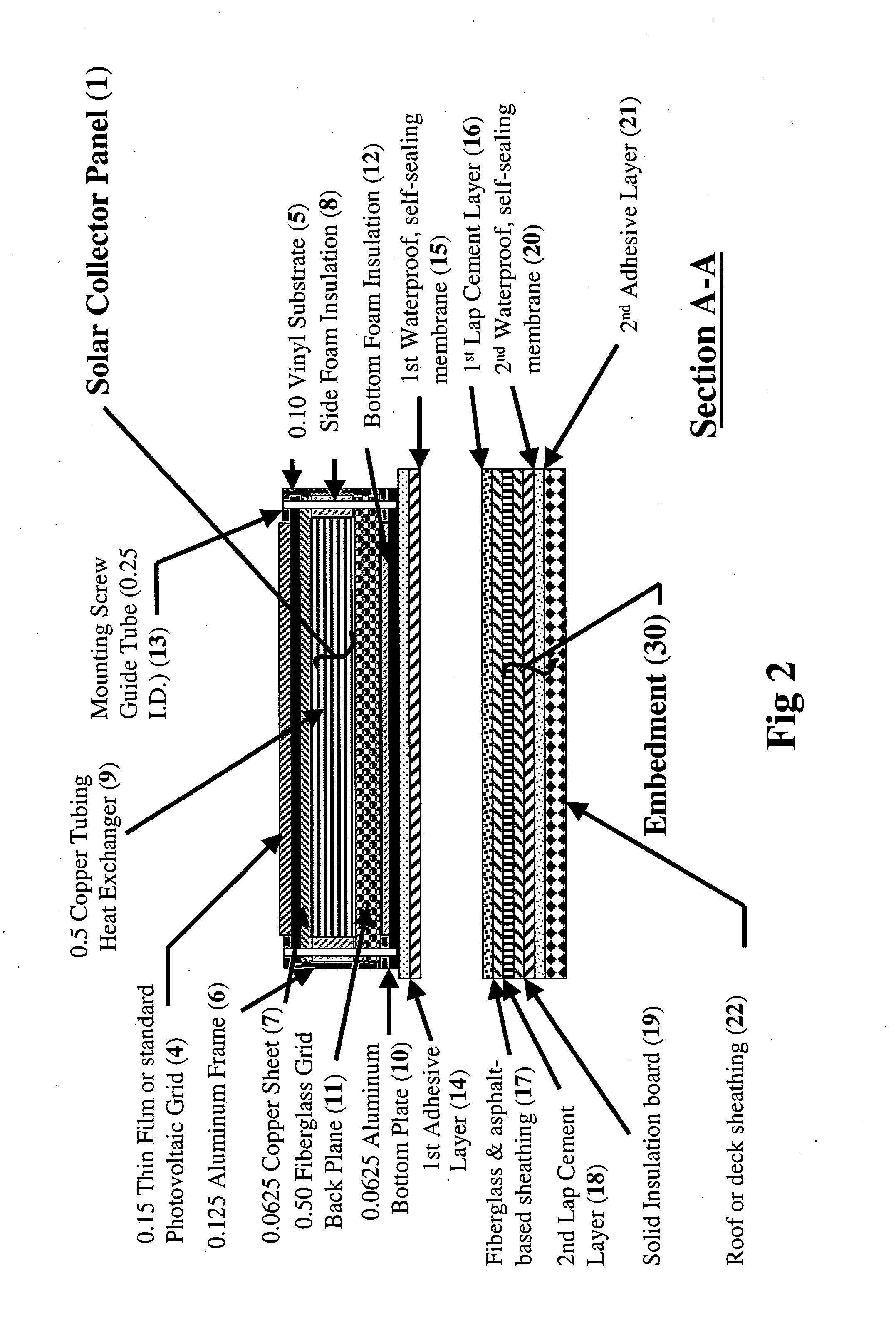
[0042] As the apparatus, FIG. 2, is a section view A-A of the solar collector panel (1) and a separate embedment assembly that are both constructed as a sandwich of component layers. The collector components are contained within a rectangular frame with an open topside and an open bottom side. The first layer of the Solar Panel (1) is a photovoltaic (PV) grid (4) held in place by an overlaying lip formed on the top of frame (6) side members. The PV grid includes a thin glass cover sheet for weather protection. Supporting the photovoltaic grid (4) is a 0.10-inch clear Vinyl substrate (5). The photovoltaic grid (4) consists of multiple commercial thin film or crystalline cell panel units available from sources such as UniSolar, Sharp, Kyocera, and Shell. Below the PV grid is mounted a 0.0625-inch copper sheet (7) for uniform and efficient heat transfer as absorption and radiation to or from a copper tubing heat exchanger (9). For maximum heat transfer, the copper tubing heat exchanger...

second embodiment

[0045] Again, as shown in FIG. 2 section view A-A of the solar collector panel (1) the apparatus is formed where the first layer is a thin-film photovoltaic grid (4) vacuum deposited on a 0.10-inch clear Vinyl substrate (5). The Vinyl substrate (5) is held in place by an overlaying lip formed on the top of frame (42) side members. Below that is mounted a heat transfer 0.0625-inch copper sheet (7) for uniform and efficient heat absorption and radiation. For maximum heat transfer, a copper tubing heat exchanger (9) is bonded to the copper sheet (7) using a thermal conducting compound. In the preferred embodiment, the compound is a copper-filled epoxy. The copper tubing heat exchanger (9) is thermally isolated by side foam insulation (8) that lies between the copper tubing heat exchanger (9) and the frame (42).

[0046] Below the copper tubing heat exchanger (9) is a 0.50-inch fiberglass back plane (11) that provides rigid structural support for the heat exchanger (9) and the photovoltaic...


PUM


Abstract

A solar assembly comprising two components: a multi-functional solar collecting apparatus and a mounting embedment integrated with building construction material. The mounting embedment component is affixed to a building frame structure using standard construction techniques and receives the multi-functional solar collecting apparatus that is secured with fasteners. The multi-functional solar collecting apparatus converts solar energy to electrical energy using a photovoltaic grid mounted on a copper plate that provides even temperature dispersion across the plate and acts as a thermal radiator when the apparatus is used as a radiant cooler; and a plurality of interconnected heat transfer tubes located within the apparatus enclosure disposed on the plane below the copper plate but conductively coupled to the copper plate for converting the solar energy to thermal energy in a fluid disposed within the heat transfer tubes.

Description

CROSS-REFERENCE TO RELATED APPLICATIONS [0001] Not Applicable STATEMENT REGARDING FEDERALLY SPONSORED RESEARCH OR DEVELOPMENT [0002] Not applicable REFERENCE TO A “SEQUENCE LISTING,” A TABLE, OR A COMPUTER PROGRAM LISTING APPENDIX SUBMITTED ON A COMPACT DISC [0003] Not Applicable BACKGROUND OF THE INVENTION [0004] (1) Field of the Invention [0005] The present invention relates to the use of solar energy for conversion of solar energy to electrical and thermal energy with the added function of radiant cooling for general use with industrial / commercial processes requiring working fluid cooling; and improved by providing a prepared embedment component integrated with roofing or insulation materials to simplify the invention installation and to shorten the amount of required labor. [0006] (2) Description of the Related Art [0007] Over the last several decades, great strides have been made in the development of apparatus for the conversion of solar energy to thermal or electrical energy ...

Claims


Application Information

Patent Timeline
Patent Type & Authority Applications(United States)
IPC IPC(8): F24J2/46F24J2/52H01L25/00H01L31/052H01L31/058
CPCF24J2/045F24J2/085F24J2/265Y02B10/12H01L31/0543Y02B10/70Y02E10/52Y02E10/60H02S40/44Y02B10/20F24S10/753F24S20/67F24S23/31Y02B10/10
Inventor KONOLD, ANNEMARIE HVISTENDAHLKONOLD, DONALD ROSS
Owner KONOLD ANNEMARIE HVISTENDAHL
Why Eureka
Try Eureka