Microfluidic control device and method for controlling microfluid
What is Al technical title?
Al technical title is built by PatSnap Al team. It summarizes the technical point description of the patent document.
a microfluidic and control device technology, applied in the direction of positive displacement liquid engines, machines/engines, laboratory glassware, etc., can solve the problems of high power consumption, difficult to fabricate the structure and control reaction time, and high cos
Inactive Publication Date: 2005-06-23
ELECTRONICS & TELECOMM RES INST
View PDF5 Cites 84 Cited by
Summary
Abstract
Description
Claims
Application Information
AI Technical Summary
This helps you quickly interpret patents by identifying the three key elements:
Problems solved by technology
Method used
Benefits of technology
[0019] Another aspect of the present invention is to provide a method for controlling a microfluidic control device, which comprises the steps of providing fluid flown from outside to a reaction chamber; stopping the fluid provided from the reaction chamber by means of capillary force; removing a boundary surface of the fluid stopped at the stop valve by the injection of a droplet, leading to the loss of a function of the stop valve to allow the fluid to continuously flow.
Problems solved by technology
The U.S. Pat. No. 6,271,040 B1 discloses a bio chip structure for diagnosis, which transports sample only using flow resulted from capillary force and increases transport time using pressure increase of the structure while the samples are subject to reaction in a chamber, and determines whether the samples react with an optical method, however, its structure is complicated, which causes it difficult to fabricate the structure and to control reaction time.
The U.S. Pat. No. 6,143,248 discloses a microvalve for transporting a fine amount of fluid from a micro storage chamber to a transfer chamber by controlling capillary and centrifugal forces, however, it should disadvantageously apply the centrifugal force so as to perform reflow after the fluid is stopped.
The U.S. Pat. No. 6,130,098 discloses a microfluidic device for transporting a predetermined amount of small volume fluid by means of thermo-pneumatic pressure and stop valve with hydrophobic surface, however, it requires an additional structure for pumping and high power consumption.
As mentioned above, additional mechanical device or electrical device is used to control fluid in the related art, which cause its configuration to be complicated and fabrication cost to be increased.
Method used
Image
Click on the blue label to locate the original text in one second.
Reading with bidirectional positioning of images and text.
Examples
Embodiment Construction
[0033] The present invention will now be described more fully hereinafter with reference to the accompanying drawings, in which preferred embodiments of the field emission device are shown. This invention may, however, be embodied in different forms and should not be construed as limited to the embodiments set forth herein. Rather, these embodiments are provided so that this disclosure will be thorough and complete, and will fully convey the scope of the invention to those skilled in the art. In the drawings, the thickness of layers and regions are exaggerated for clarity. Like numbers refer to like elements throughout the specification.
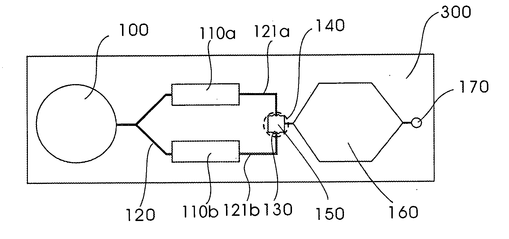
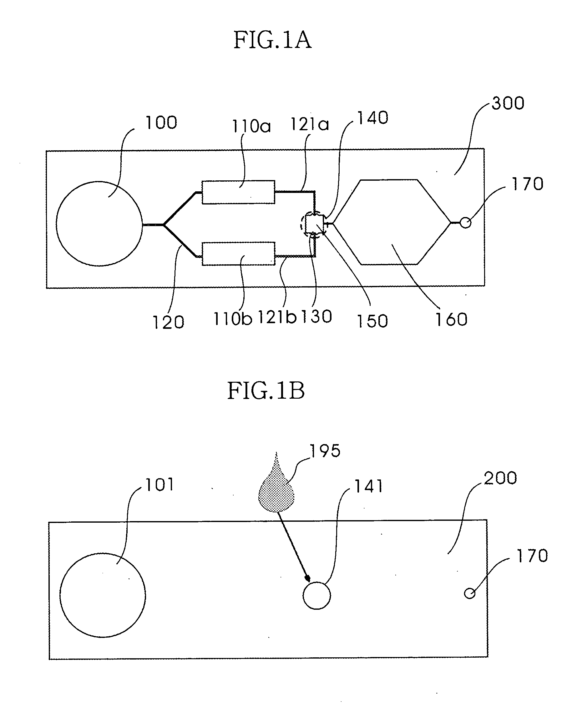
[0034] The present invention provides a microfluidic control device and method for controlling the microfluid, which implements various controls such as transport, interflow, time delay of fluid by injecting solution to change capillary force. Injecting solution in the present invention means a simple droplet dropping without using a device like a p...
PUM
Property
Measurement
Unit
contact angle
aaaaa
aaaaa
height
aaaaa
aaaaa
capillary force
aaaaa
aaaaa
Abstract
Provided is a microfluidic control device and method for controlling the microfluid, and a fine amount of fluid is controlled even with natural fluid flow and solution injection, wherein a pressure barrier of a capillary is removed by a surface tension change resulted from the solution injection to thereby obtain transport, interflow, mixing, and time delay of the microfluid, and to detail this, solution is injected to meet the boundary surface of the stopped fluid when the fluid is stopped by the stop valve, so that a function of the stop valve is removed to obtain the transport, interflow, and mixing of the fluid, and the method for controlling the microfluid may be applied to the microfluidic control device for biochemical reaction, and it uses only the capillary force change resulted from solution injection to thereby have its structure simplified.
Description
BACKGROUND [0001] 1. Field of the Invention [0002] The present invention generally relates to a microfluidic control device and method for controlling the same, and more particularly, to a microfluidic control device and method for controlling the same, which allows a pressure barrier to be removed by means of a surface tension change resulted from solution drop, thereby enabling transport, confluence, mixing, and time delay of the microfluid. [0003] 2. Discussion of Related Art [0004] In order to configure a bio chip, a bio sensor, a chemical sensor and so forth for a biochemical analysis, a complicated fluid network for microfluidic control such as transport, stop, mixing, reaction, exchange and confluence, a valve capable of operating in a chamber, a pump, and so forth are required. To that end, various driving methods are proposed, for example, mechanical pumping, thermopneumatic pumping, an electrostatic actuation, an electrophoretic method, electrochemical actuation, and a cap...
Claims
Application Information
Patent Timeline
Application Date:The date an application was filed.
Publication Date:The date a patent or application was officially published.
First Publication Date:The earliest publication date of a patent with the same application number.
Issue Date:Publication date of the patent grant document.
PCT Entry Date:The Entry date of PCT National Phase.
Estimated Expiry Date:The statutory expiry date of a patent right according to the Patent Law, and it is the longest term of protection that the patent right can achieve without the termination of the patent right due to other reasons(Term extension factor has been taken into account ).
Invalid Date:Actual expiry date is based on effective date or publication date of legal transaction data of invalid patent.
Patent Type & Authority Applications(United States)