
Apparatuses and methods for suppressing thermally-induced motion of a workpiece

a technology of workpieces and apparatuses, applied in lighting and heating apparatus, muffle furnaces, furnaces, etc., can solve the problems of large downward force applied to the edges of the wafer, damage to the wafer, and insufficient deformation of the wafer, so as to reduce the likelihood of breakage or damage to the workpiece, the effect of increasing the pressur

Active Publication Date: 2005-06-23
MATTSON TECHNOLOGY +1
View PDF99 Cites 47 Cited by
  • Summary
  • Abstract
  • Description
  • Claims
  • Application Information

AI Technical Summary

Benefits of technology

[0011] Advantageously, as the damping member is spaced apart from the workpiece, direct mechanical contact between the damping member and the workpiece can be avoided, thereby reducing the likelihood of breakage or damage to the workpiece.
[0012] The damping member is preferably spaced apart from a rest position of the workpiece by a distance sufficiently small that gas pressure between the damping member and the workpiece opposes the motion of the workpiece. For example, if the workpiece is a semiconductor wafer supported a small distance above the damping member, the irradiance flash may cause the central region of the wafer to rapidly rise upward away from the damping member. This creates a low gas pressure zone in the gap between the wafer and the damping member. Thus, a pressure differential is created, between the higher ambient pressure above the wafer, and the lowered pressure in the gap beneath the wafer, which tends to oppose the upward motion of the wafer. Conversely, if the central region of the wafer comes back downward and overshoots its planar equilibrium position, this creates a higher pressure in the gap between the wafer and the damping member than the ambient pressure above the wafer, so that the pressure differential continuously opposes the motion of the wafer as it oscillates or vibrates. Thus, motion and vibration of the wafer are dampened, without the necessity of potentially damaging physical contact between the wafer and the damping member.
[0022] The distance between the damping member and the workpiece may be adjustable to adjust the damping force. For example, the distance between the damping member and the workpiece may be adjustable between a first distance employable during the pre-heating stage, and a second distance smaller than the first distance employable during the irradiance flash and a motion-damping stage thereafter. The first distance may be at least two millimeters. As a further example, the first distance may be on the order of one centimeter. Advantageously, as the first distance used during the pre-heating stage is larger than the second distance used during the irradiance flash and the subsequent motion-damping stage, thermal coupling effects are reduced during the pre-heating stage. The second distance may be sufficiently small that gas pressure between the damping member and the workpiece opposes the motion of the workpiece during the irradiance flash and the motion-damping stage. For example, the second distance may be about one millimeter. As a further example, the second distance may be about one-half millimeter. In addition to the first and second distances, the distance may be further adjustable to a third distance greater than the second distance, employable during a subsequent cooling stage following the motion-damping stage. Advantageously, as the third distance used for the cooling stage is larger than the second distance used for the irradiance flash and the motion-damping stage, thermal coupling effects are also reduced during the cooling stage. For example, the third distance may be at least two millimeters. Advantageously, therefore, as discussed herein, such adjustability reduces thermal coupling effects between the workpiece and the damping member during both the pre-heating and subsequent cooling stages, while allowing the damping member to suppress thermally induced motion of the workpiece during the irradiance flash and subsequent motion-damping stage.
[0039] The method may include adjusting the distance between the damping member and the workpiece. This may include maintaining a first distance between the damping member and the workpiece during the pre-heating stage, and maintaining a second distance smaller than the first distance between the damping member and the workpiece during the irradiance flash and a motion-damping stage thereafter. Maintaining the first distance may include maintaining a distance of at least two millimeters between the damping member and the workpiece during the pre-heating stage. Maintaining the second distance may include maintaining a distance sufficiently small that gas pressure between the damping member and the workpiece opposes the motion of the workpiece during the irradiance flash and the motion-damping stage. This may include maintaining a distance of about one millimeter between the damping member and the workpiece during the irradiance flash and the motion-damping stage. Alternatively, this may include maintaining a distance of about one-half millimeter between the damping member and the workpiece during the irradiance flash and the motion-damping stage. The method may further include maintaining a third distance greater than the second distance between the damping member and the workpiece during a subsequent cooling stage following the motion-damping stage. Maintaining the third distance may include maintaining a distance of at least two millimeters between the damping member and the workpiece during the cooling stage. Advantageously, as the first and third distances are greater than the second distance, thermal coupling effects are reduced during the pre-heating and cooling stages, while allowing for adequate motion damping during the irradiance flash and the motion-damping stage.

Problems solved by technology

However, due to the extreme rapidity at which the device side of the wafer is heated (in the course of a 1-millisecond flash, for example, much faster than a typical thermal conduction time in the wafer), the deformation of the wafer may occur sufficiently rapidly that the edges of the wafer apply a large downward force onto the support pins that support the wafer in the chamber.
As conventional support pins are typically rigid, the resulting reaction force between the pins and the edges of the wafer may damage the wafer.
Such forces may also cause the wafer to launch itself vertically upward from the support pins, which may result in further damage to the wafer as the wafer falls back down and strikes the pins.
Also, as conventional support pins are not designed to withstand such forces, they tend to break, with the result that the wafer falls in the chamber and is damaged or destroyed.
In addition, due to the rapidity at which such thermal bowing occurs, the initial velocities imparted to the various regions of the wafer tend to cause the wafer to overshoot the equilibrium minimum stress shape and oscillate or vibrate, resulting in additional stress and potential damage to the wafer.
As a result, the wafer tends to break, particularly if the magnitude of the “jump” (i.e., the difference between the intermediate temperature and the ultimate device-side temperature) is large.
Thus, such constrictive approaches to suppressing motion or vibration of the wafer are undesirable.

Method used


Image

  • Apparatuses and methods for suppressing thermally-induced motion of a workpiece
  • Apparatuses and methods for suppressing thermally-induced motion of a workpiece
  • Apparatuses and methods for suppressing thermally-induced motion of a workpiece

Examples


first embodiment

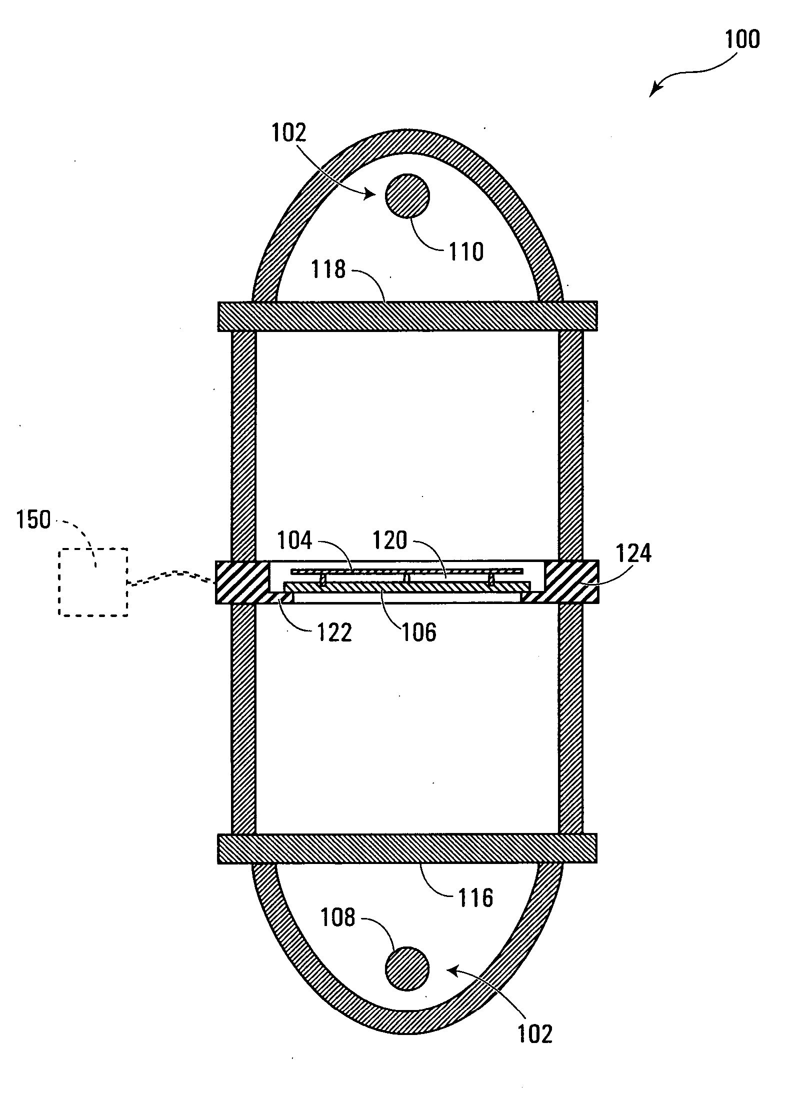
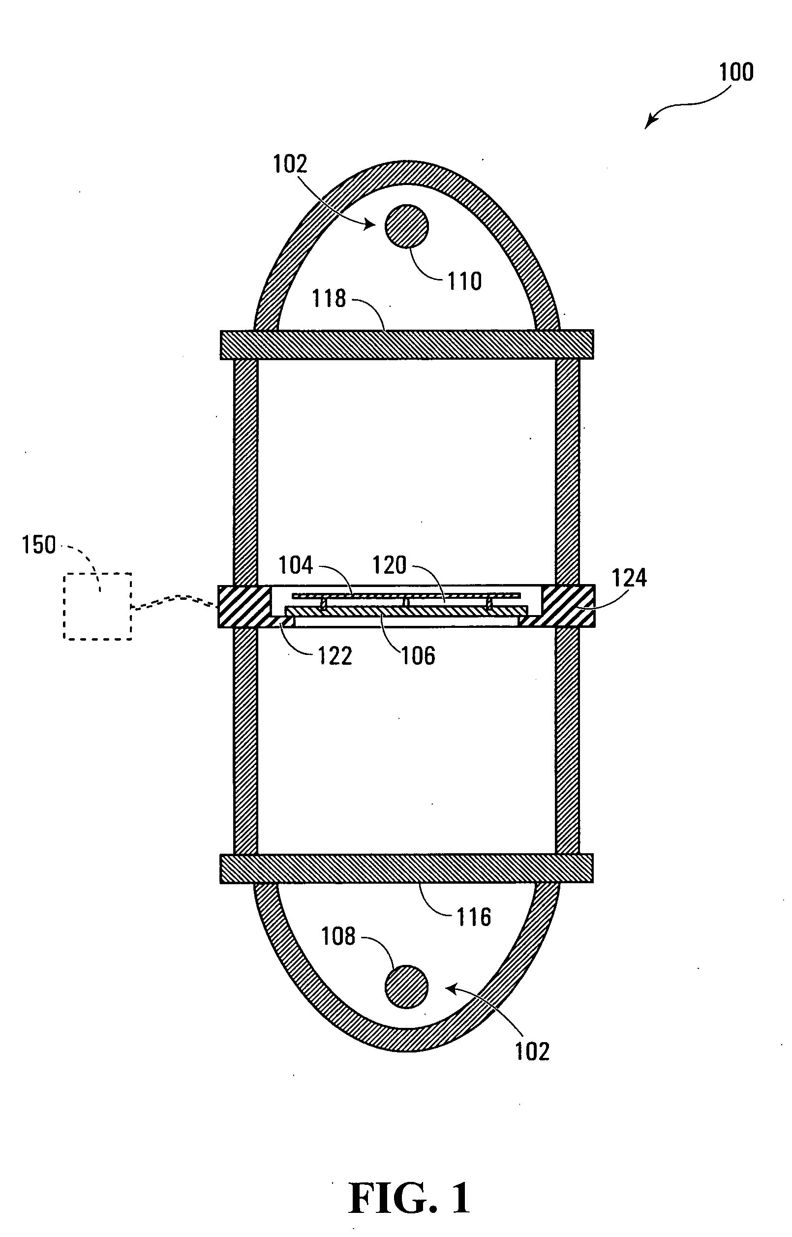
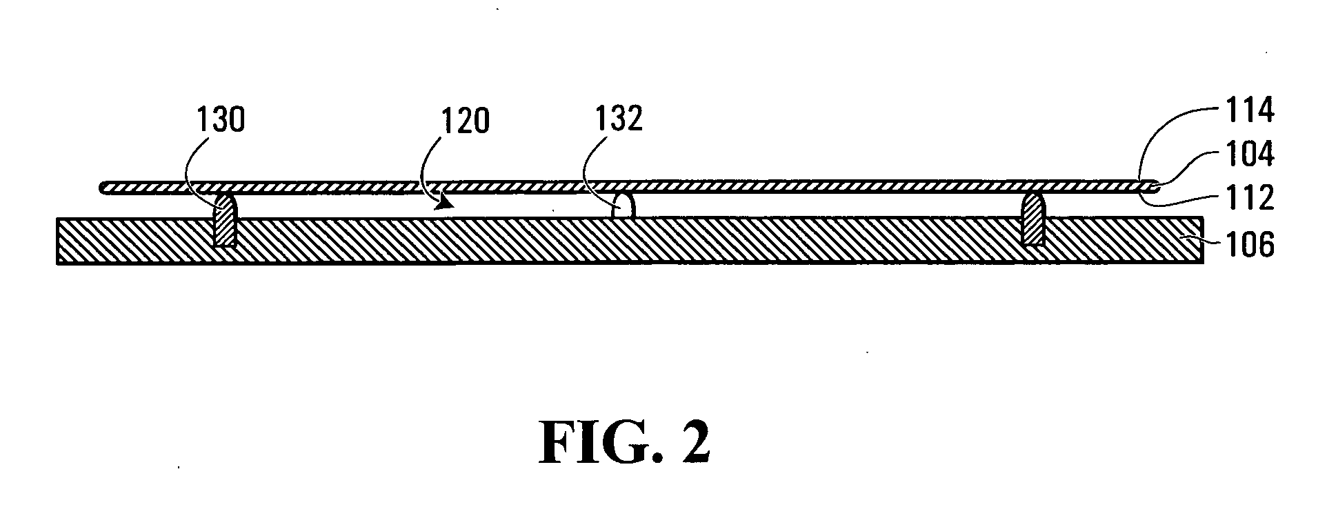
[0054] Referring to FIGS. 1 and 2, an apparatus for suppressing thermally induced motion of a workpiece according to the invention is shown generally at 100. In this embodiment, the apparatus 100 includes a workpiece heating system shown generally at 102, configured to thermally induce motion of the workpiece 104, which in this embodiment is achieved by heat-treating the workpiece in a manner that thermally induces such motion. In the present embodiment, the apparatus 100 further includes a damping member 106, spaced apart from the workpiece 104 and configured to apply a damping force to dampen the motion of the workpiece.

[0055] In this embodiment, the heating system 102 includes a pre-heating system configured to pre-heat the workpiece to an intermediate temperature, and a surface heating system configured to heat only a surface region of the workpiece to a desired temperature greater than the intermediate temperature. In this embodiment, each of the pre-heating system and the surf...

second embodiment

[0067] Referring to FIG. 3, the damping member 106 need not be below the workpiece 104, but may be above the workpiece if desired. For example, an apparatus for suppressing thermally induced motion of a workpiece according to the invention is shown generally at 300 in FIG. 3. The apparatus 300 includes a modified workpiece plane plate 302, which acts as a support system configured to support the workpiece below the damping member. The workpiece plane plate 302 supports the workpiece 104 using a plurality of flexible quartz fiber supports such as that shown at 304, as disclosed in the above-noted U.S. application publication No. US 2004 / 0178553 A1. The workpiece plane plate 302 further includes an annular inwardly-protruding supporting edge for supporting the damping member 106 at a desired gap distance above the rest position of the workpiece 104. In this embodiment, as the damping member 106 is thus interposed between the flash lamp 110 and the workpiece 104, it is transparent to t...

third embodiment

[0068] Referring to FIGS. 1 and 4, an apparatus for suppressing thermally induced motion according to the invention is shown generally at 400 in FIG. 4. The apparatus 400 includes a workpiece plane plate 402, having a lower annular inwardly-protruding supporting edge 404, for supporting the damping member 106, in a manner similar to the embodiment shown in FIG. 1. However, in this embodiment the apparatus 400 further includes a second damping member 406, supported by an upper annular inwardly-protruding supporting edge 408 of the workpiece plane plate 402. In this embodiment, the support pins protruding upwardly from the first damping member 106 act as a support system configured to support the workpiece above the first damping member and below the second damping member. In this embodiment, the gap 120 between the back-side 112 of the workpiece and the damping member 106 is similar to that of the previous embodiment, i.e., preferably on the order of one-half millimeter to three mill...


PUM

PropertyMeasurementUnit
distanceaaaaaaaaaa
distanceaaaaaaaaaa
distanceaaaaaaaaaa

Abstract

Apparatuses and methods for suppressing thermally induced motion of a workpiece. An apparatus includes a workpiece heating system configured to thermally induce motion of a workpiece, and further includes a damping member spaced apart from the workpiece and configured to apply a damping force to dampen the motion of the workpiece. The damping member may be spaced apart from a rest position of the workpiece by a distance sufficiently small that gas pressure between the damping member and the workpiece opposes the motion of the workpiece. The distance is preferably adjustable.

Description

CROSS-REFERENCE TO RELATED APPLICATIONS [0001] This application claims the benefit of priority from U.S. patent application Ser. No. 60 / 568,685 filed May 7, 2004, and is a continuation-in-part of U.S. patent application Ser. No. 10 / 742,575 filed Dec. 19, 2003, both of which are hereby incorporated herein by reference.BACKGROUND OF THE INVENTION [0002] 1. Field of Invention [0003] The present application relates to methods and apparatuses for suppressing thermally induced motion of a workpiece. [0004] 2. Description of Related Art [0005] Numerous applications involve thermally induced motion of a workpiece. For example, in the manufacture of semiconductor chips such as microprocessors, the workpiece typically includes a semiconductor wafer, supported in a thermal processing chamber for annealing or other heat-treating purposes. U.S. patent application Ser. No. 10 / 742,575 (publication no. US 2004 / 0178553 A1), discusses examples of heat-treating techniques for annealing such semiconduc...

Claims


Application Information

Patent Timeline
Patent Type & Authority Applications(United States)
IPC IPC(8): B25B11/00H01L21/00H01L21/68
CPCH01L21/67115H01L21/6875H01L21/67288
Inventor CAMM, DAVID MALCOLMBUMBULOVIC, MLADENCIBERE, JOSEPHELLIOTT, J. KIEFERMCCOY, STEVESTUART, GREG
Owner MATTSON TECHNOLOGY
Features
  • Generate Ideas
  • Intellectual Property
  • Life Sciences
  • Materials
  • Tech Scout
  • Unparalleled Data Quality
  • Higher Quality Content
  • 60% Fewer Hallucinations
Learn More