Explosives detection using differential ion mobility spectrometry

a technology of differential ion mobility and ion ion, applied in the field of explosive detection using differential ion mobility spectrometry, can solve the problems of large mass spectrometers, relatively difficult field deployment of mass spectrometers, and high cost of mass spectrometers, so as to improve detection sensitivity, improve resolution, and enhance separation of ion species

a technology of differential ion mobility and ion ion, applied in the field of explosive detection using differential ion mobility spectrometry, can solve the problems of large mass spectrometers, relatively difficult field deployment of mass spectrometers, and high cost of mass spectrometers, so as to improve detection sensitivity, improve resolution, and enhance separation of ion species

US20050133716A1Inactive Publication Date: 2005-06-23DH TECH DEVMENT PTE

Image

  • Explosives detection using differential ion mobility spectrometry
  • Explosives detection using differential ion mobility spectrometry
  • Explosives detection using differential ion mobility spectrometry

Examples


Embodiment Construction

[0047] In general, the invention is directed to systems and methods for detecting and identifying unknown constituents in chemical substances by aspects of differential ion mobility. In particular, the systems and methods described herein can be used to detect explosives-related compounds, whether explosives material per se or taggants or the like used with explosives, using DMS technology.

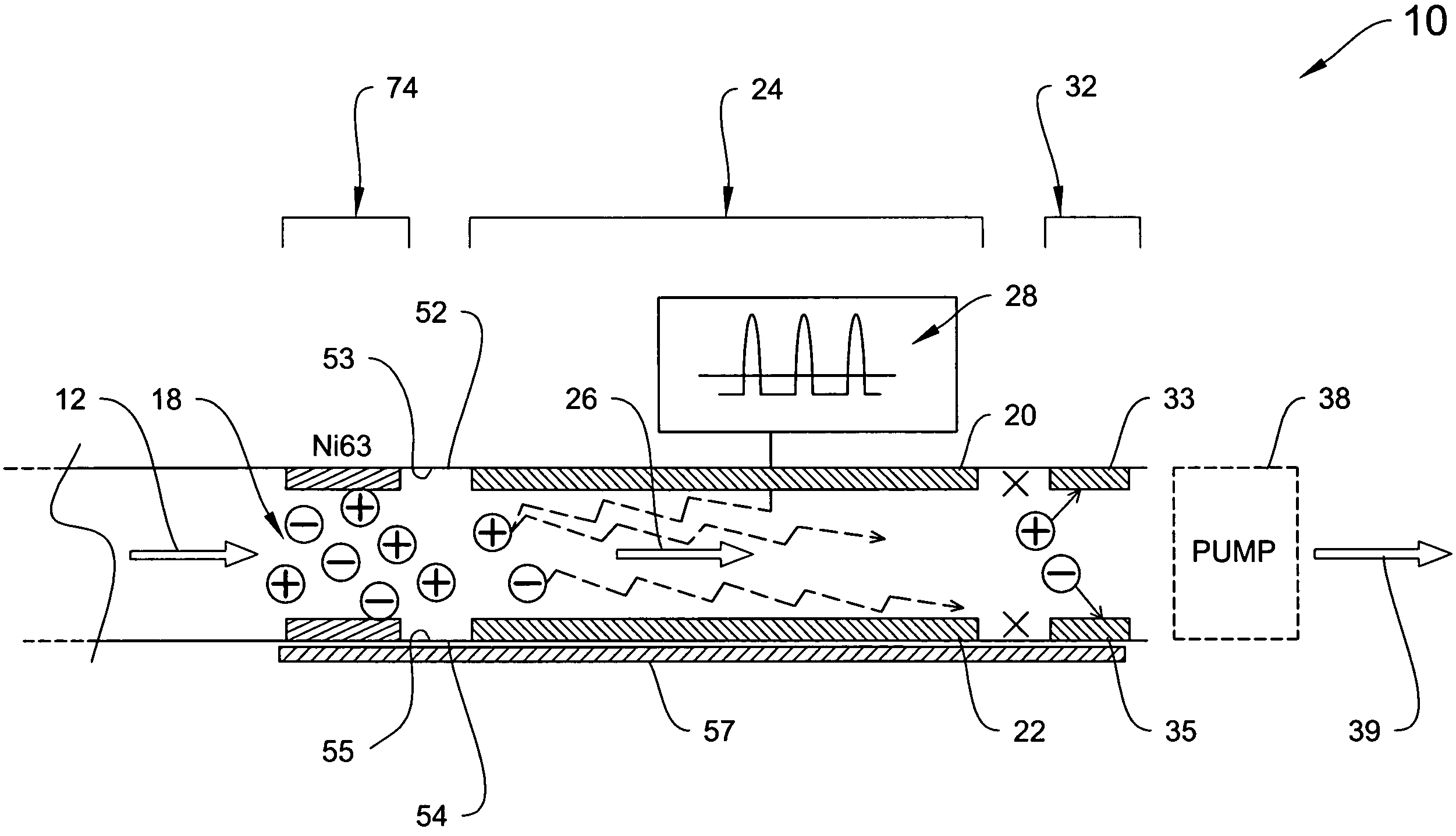
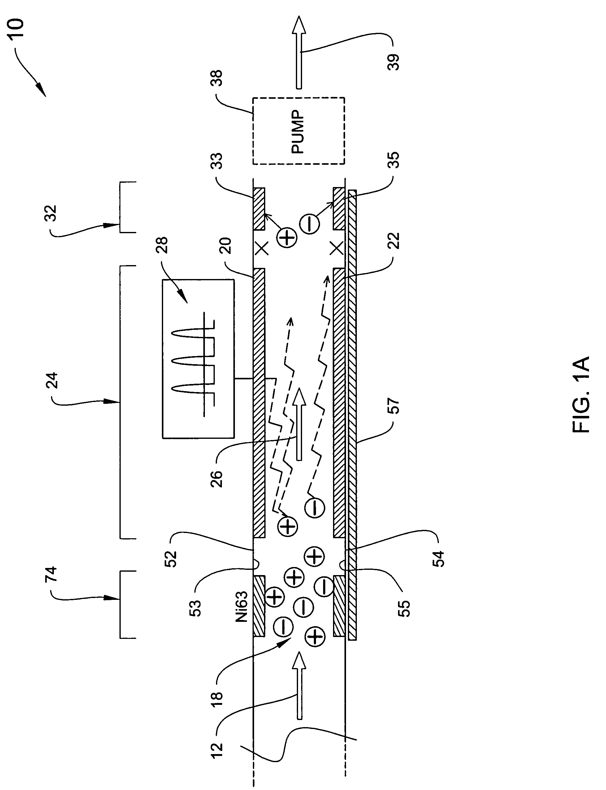
[0048] An illustrative DMS system of the invention is shown in FIG. 1A, which is a schematic block diagram of a DMS spectrometer 10, which operates by drawing a fluid (e.g., gas), indicated by arrow 12, via an optional pump 38 into an ionization region 18. The sample flow, e.g., a gas flow carrying an analyte(s) to be detected, is subjected to an ionization source, wherein at least the analyte is ionized although the carrier gas is normally part of the ionization process as well, for example by a radioactive 63Ni source, UV lamp, plasma source, or the like.

[0049] The ionized sample passes betwee...


PUM

PropertyMeasurementUnit
velocityaaaaaaaaaa
residence timeaaaaaaaaaa
widthaaaaaaaaaa

Abstract

System for control of ion species behavior in a time-varying filter field of an ion mobility-based spectrometer to improve species identification for explosives detection.

Description

CROSS-REFERENCE TO OTHER PATENT APPLICATIONS [0001] This application is a continuation-in-part of U.S. patent application Ser. No. 10 / 187,464, filed Jun. 28, 2002, and a continuation-in-part of U.S. patent application Ser. No. 10 / 462,206, filed Jun. 13, 2003, and also a continuation-in-part of U.S. patent application Ser. No. 10 / 321,822, filed Dec. 16, 2002, which is a continuation-in-part of U.S. patent application Ser. No. 09 / 358,312, filed Jul. 21, 1999, now U.S. Pat. No. 6,495,823 B1. This application also claims the benefit of U.S. Provisional application No. 60 / 461,282, filed Apr. 8, 2003 and U.S. Provisional application No. 60 / 530,518, filed Dec. 18, 2003, the entire contents thereof are incorporated herein by reference in their entirety.FIELD OF THE INVENTION [0002] The present invention relates generally to identification of unknown constituents of a sample by their ion mobility characteristics in an electric field, and more particularly to devices and methods that analyze ...

Claims


Application Information

Patent Timeline
23 Jun 2005
Publication
US20050133716A1
IPC
G01N27/64; G01N33/22
CPC
G01N27/624; H01J49/0018; G01N33/22
Inventors
MILLER, RAANAN A.; NAZAROV, ERKINJON G.