Apparatus and method for controlled combustion of gaseous pollutants

Active Publication Date: 2005-06-23
BHT SERVICES PTE LTD
View PDF31 Cites 88 Cited by
  • Summary
  • Abstract
  • Description
  • Claims
  • Application Information

AI Technical Summary

Benefits of technology

[0011] The present invention relates to methods and systems for providing controlled combustion of gaseous se

Problems solved by technology

Semiconductor manufacturing processes utilize a variety of chemicals, many of which have extremely low human tolerance levels.
Halogens, e.g., fluorine (F2) and fluorinated compounds are particularly problematic among the various components requiring abatement.
A significant problem has been the removal of these materials from effluent gas streams of semiconductor manufacturing processes.
While virtually all U.S. semiconductor-manufacturing facilities utilize scrubbers or similar means for treatment of their effluent gases, the technology employed in these facilities is not capable of removing all toxic or otherwise unacceptable impurities.
Such systems are almost always over-designed in terms of its treatme

Method used


Image

  • Apparatus and method for controlled combustion of gaseous pollutants
  • Apparatus and method for controlled combustion of gaseous pollutants
  • Apparatus and method for controlled combustion of gaseous pollutants

Examples


Embodiment Construction

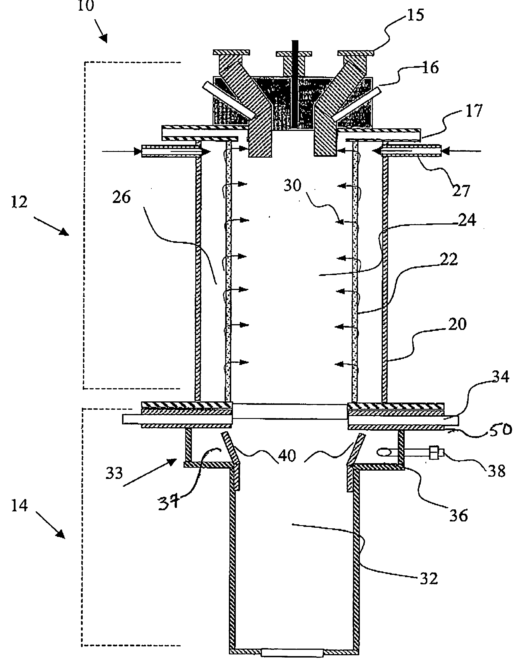
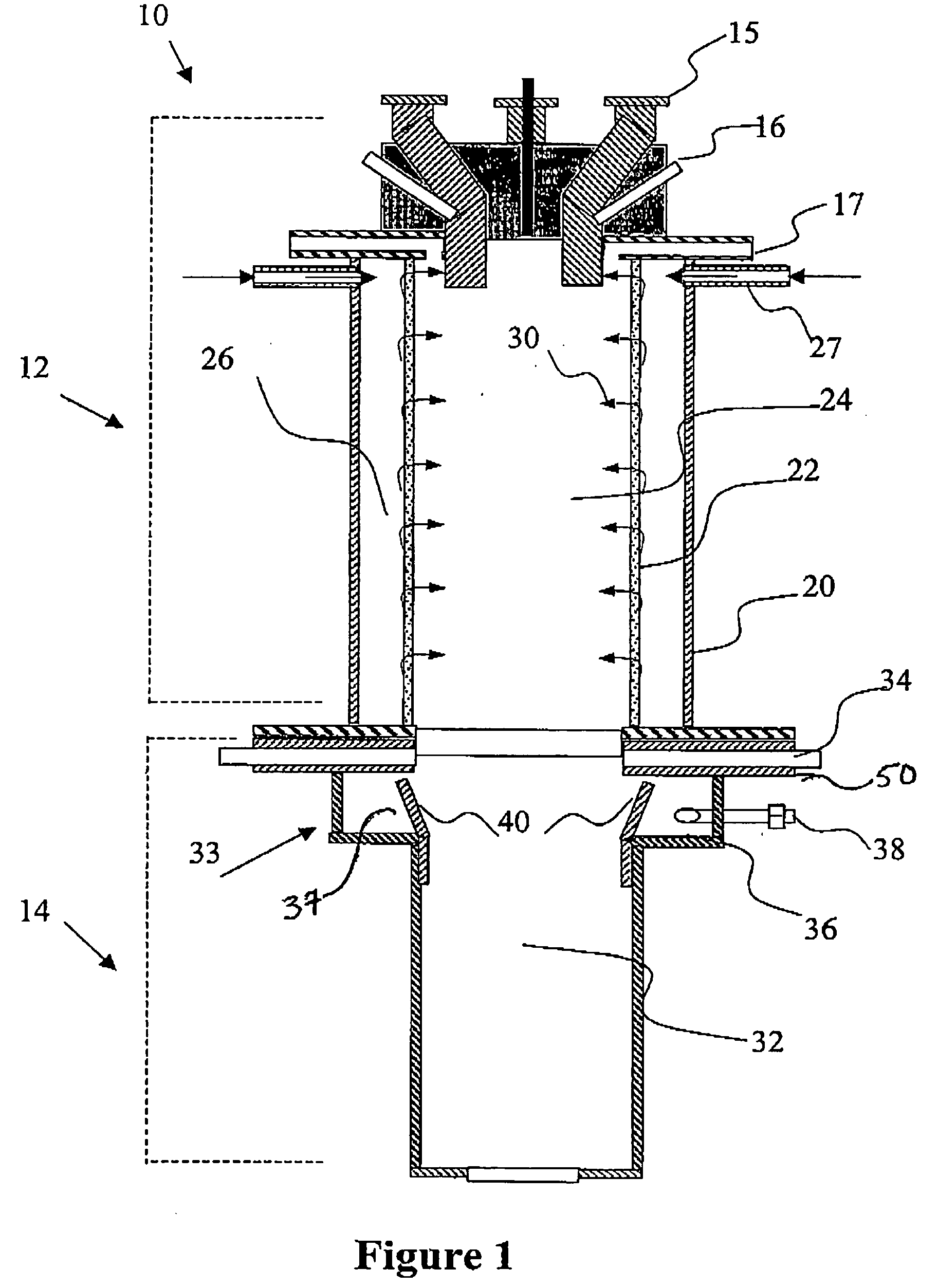
[0056] With reference to FIG. 1, there is shown a two-stage reactive 10 representative of the system described herein. There is shown an upper reaction chamber 12 and a lower reaction chamber 14. The upper reaction chamber includes at least one waste gas inlet 15 for introducing the gaseous waste stream. In this embodiment, there are additional independent gas inlets 16 and 17 for the introduction of additional flammable gases or oxidants to provide a fuel rich gas mixture and thereby increasing the combustion temperature within the system for destruction of resistant contaminates.

[0057] The upper reaction chamber further comprises an outer exterior wall 20 made of an ordinary metallic material and an interior wall 22 made of a porous material that circumvent a central combustion chamber 24. The interior porous wall is positioned from the outer exterior wall a sufficient distance to define an interior annular space 26. The annular space 26 is provided for introducing a fluid, prefe...


PUM

PropertyMeasurementUnit
Timeaaaaaaaaaa
Timeaaaaaaaaaa
Pressureaaaaaaaaaa

Abstract

The present invention relates to systems and methods for controlled combustion of gaseous pollutants while reducing and removing deposition of unwanted reaction products from within the treatment systems. The systems employ a two-stage thermal reactor having an upper thermal reactor including at least one inlet for mixing a gaseous waste stream with oxidants and combustible fuels for thermal combustion within the upper thermal reactor. The upper thermal reactor further includes a double wall structure having an outer exterior wall and an interior porous wall that defines an interior space for holding a fluid and ejecting same, in a pulsating mode, through the interior porous wall into the upper thermal reactor to reduce deposition of the reaction products on the interior of the upper reactor chamber. The two-stage thermal reactor further includes a lower reactor chamber for flowing reaction products formed in the upper thermal reactor through a water vortex that provides a water overflow along the interior of the lower reactor chamber thereby reducing deposition of unwanted products on the interior surface of the lower reactor.

Description

BACKGROUND OF THE INVENTION [0001] 1. Field of the Invention [0002] The present invention relates to systems and methods for thermal treatment of industrial effluent fluids such as effluent gases produced in semiconductor manufacturing while reducing deposition of reaction products in the treatment systems. [0003] 2. Description of the Related Art [0004] The gaseous effluents from the manufacturing of semiconductor materials, devices, products and memory articles involve a wide variety of chemical compounds used and produced in the process facility. These compounds include inorganic and organic compounds, breakdown products of photo-resist and other reagents, and a wide variety of other gases that must be removed from the gaseous waste streams before being vented from the process facility into the atmosphere. [0005] Semiconductor manufacturing processes utilize a variety of chemicals, many of which have extremely low human tolerance levels. Such materials include gaseous hydrides of...

Claims


Application Information

Patent Timeline
IPC IPC(8): B01D53/34F23G7/06F23L7/00F23M5/00
CPCB01D53/34F23G7/061F23L7/00Y02E20/344F23L2900/07008F23M5/00F23M2900/05004F23L2900/07005Y02E20/34
Inventor FERRON, SHAWNKELLY, JOHNVERMEULEN, ROBBERT
Owner BHT SERVICES PTE LTD
Why Eureka
Try Eureka