Secondary air supply system and fuel injection amount control apparatus using the same

a technology of secondary air supply system and amount control apparatus, which is applied in the direction of mechanical equipment, engine components, machines/engines, etc., to achieve the effect of improving the calculation accuracy of secondary airflow rate, improving exhaust emission, and improving precision

Inactive Publication Date: 2005-06-30
DENSO CORP
View PDF10 Cites 22 Cited by
  • Summary
  • Abstract
  • Description
  • Claims
  • Application Information

AI Technical Summary

Benefits of technology

[0006] The invention has been made to solve the above-described problems of the conventional techniques, and therefore, has an object to provide a secondary air supply system of an internal combustion engine, capable of calculating a secondary airflow rate in higher precision, and capable of contributing an improvement in exhaust emission.
[0007] In the secondary air supply system of the invention, a secondary airflow rate is calculated based upon both secondary air supply pressure and reference pressure. The secondary air supply pressure is detected by a pressure sensor under such a predetermined secondary air supply condition that a secondary air supply apparatus is operated and also an opening / closing valve is opened. The reference pressure is detected by the pressure sensor under another condition different from the secondary air supply condition. In this case, since the secondary airflow rate is calculated by employing not only the secondary air supply pressure but also the reference pressure, even when product tolerance owned by the secondary air supply apparatus and product tolerance owned by the pressure sensor are presented, the calculation precision of the secondary airflow rate can be enhanced. In other words, while the secondary air supply apparatus and the pressure sensor own the product tolerance to some extent as industrial products, if the secondary airflow rate is calculated based upon such a secondary air supply pressure detected as absolute pressure, then a calculation error caused by the product tolerance and the like are produced. In contrast thereto, in accordance with the invention, since the secondary air supply pressure is converted into relative pressure so as to calculate the secondary airflow rate, the secondary airflow rate can be calculated by absorbing the product error. As a consequence, the secondary airflow rate can be calculated in higher precision, which may contribute to improve the exhaust emission.
[0008] Also, in accordance with the invention, both the pressure within the secondary air passage and the pressure within the exhaust passage are detected respectively, and then, the secondary airflow rate is calculated based upon both the detected pressure. In this case, since the secondary airflow rate is calculated by employing not only the pressure within the secondary air passage, but also the pressure within the exhaust passage, even when the pressure within the exhaust passage is changed which is caused due to change of the drive condition of the internal combustion engine, the secondary airflow rate can be calculated in higher precision. As a consequence, the exhaust emission can be improved.

Problems solved by technology

In other words, while the secondary air supply apparatus and the pressure sensor own the product tolerance to some extent as industrial products, if the secondary airflow rate is calculated based upon such a secondary air supply pressure detected as absolute pressure, then a calculation error caused by the product tolerance and the like are produced.

Method used


Image

  • Secondary air supply system and fuel injection amount control apparatus using the same
  • Secondary air supply system and fuel injection amount control apparatus using the same
  • Secondary air supply system and fuel injection amount control apparatus using the same

Examples


first embodiment

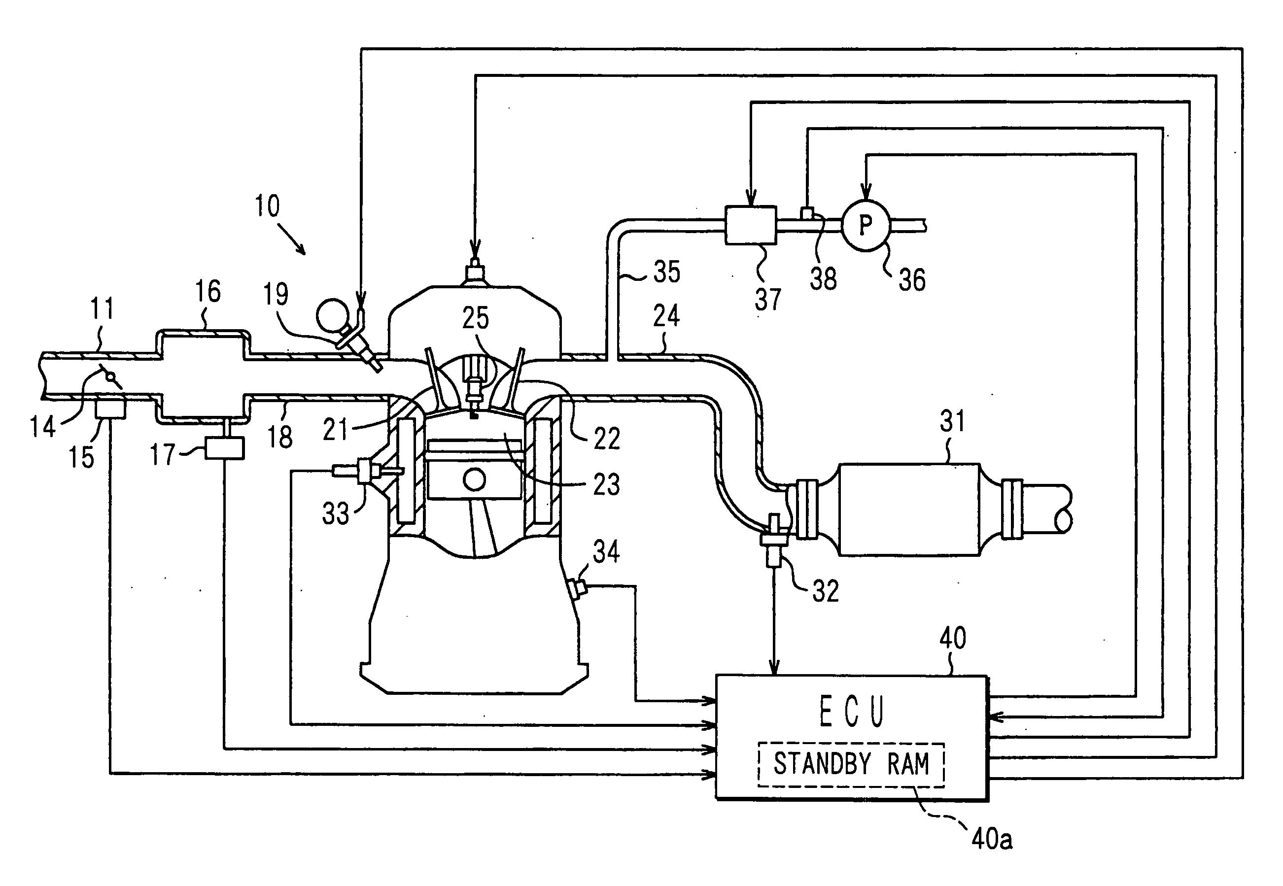
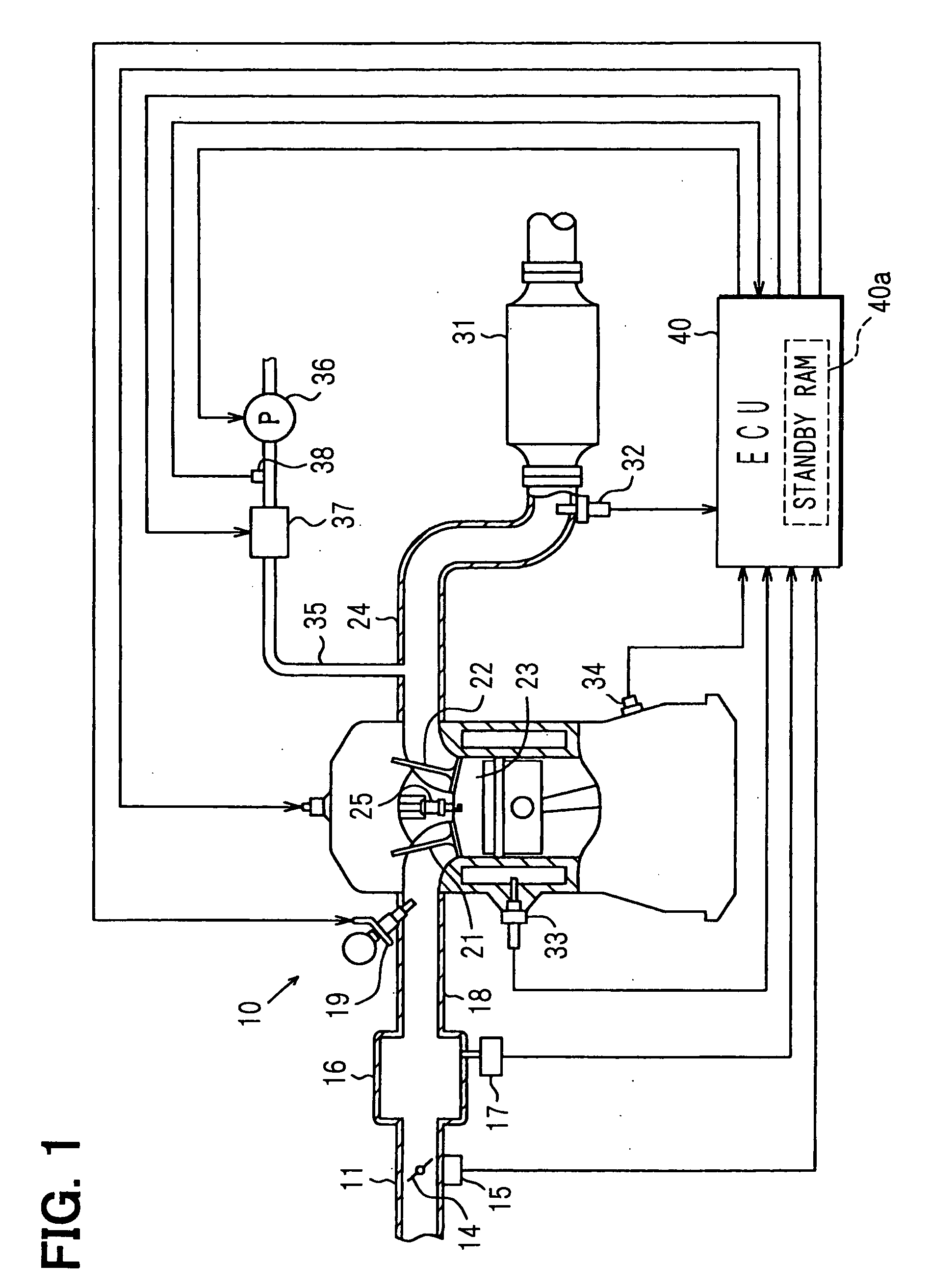
[0023] A first embodiment of the present invention is described hereinafter with reference to drawings. In this first embodiment, it is so assumed that an engine control system directed to an on-vehicle multiple cylinder gasoline engine corresponding to an internal combustion engine is constituted, and in this engine control system, an electronic control unit (will be referred to as an “ECU” hereinafter) is employed as a major unit so as to control a fuel injection amount and also to control ignition timing. FIG. 1 is an entire schematic structural diagram of the engine control system.

[0024] An engine 10 is provided with a throttle valve 14 and a throttle open degree sensor 15 in an air intake pipe 11. An open degree of the throttle valve 14 is controlled by an actuator such as a DC motor. The throttle open degree sensor 15 senses a throttle open degree. While a surge tank 16 is provided on the downstream side of the throttle valve 14, an intake pipe pressure sensor 17 for detectin...

second embodiment

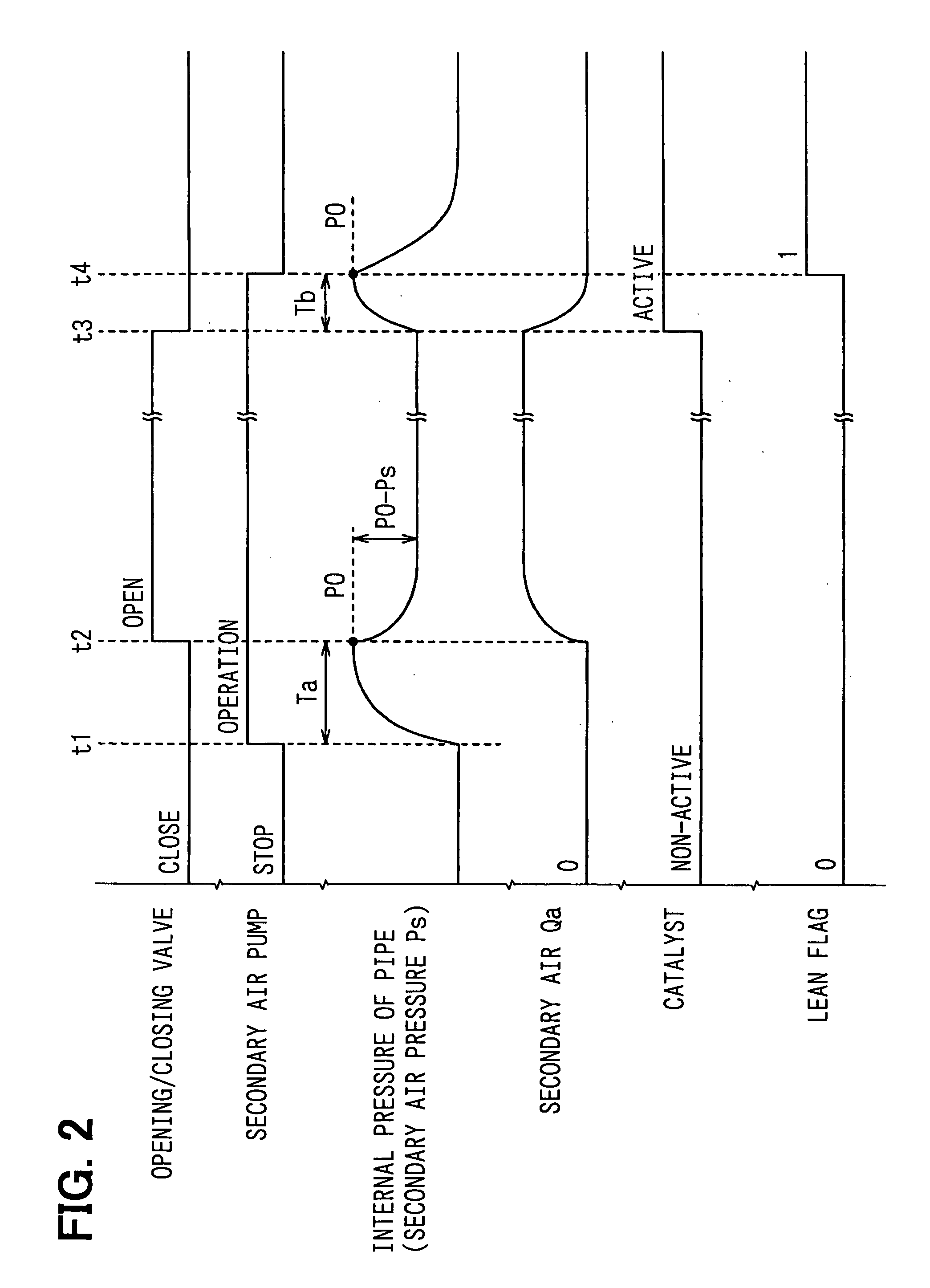
[0054] Next, in a second embodiment of the invention, a description is made of a control operation as to a fuel injection amount, while the secondary airflow rate “Qa” calculated in the above-described manner is employed, and this calculated secondary air rate “Qa” is reflected. In summary, in order that the catalyst 31 is activated in an earlier stage by supplying secondary air, for instance, an air-fuel ratio of an entrance of the catalyst 31 may be set to be a little lean. When the secondary air is supplied, a fuel injection amount control operation is carried out while the little lean air-fuel ratio is set as a target air-fuel ratio. In this case, assuming now that the air-fuel ratio is expressed by an air excess rate “λ”; an air-fuel ratio (combustion air-fuel ratio) of combustion gas used to be combustible in an engine combustion chamber is defined as “λ1”; an air-fuel ratio of an entrance of the catalyst 31 is defined as “λ2”; and an air intake amount sucked to the engine 10 ...

third embodiment

[0072] Ina third embodiment of the invention, more specifically, when a secondary air supply control operation is carried out, a secondary airflow rate “Qa” is calculated based upon both pressure within the secondary air pipe 35 (will be referred to as “secondary air supply pressure Ps” hereinafter) which is sensed by the pressure sensor 38, and pressure within the exhaust pipe 24 (will be referred to as “exhaust pressure Pex” hereinafter) which is predicted from an engine drive condition and the like. This calculation equation is given as the following equation (4):

Qa=CA{square root}{square root over (2(Ps−Pex) / ρ)}  (4)

It should be understood that in the above-described equation (4), symbol “ρ” shows fluid density; symbol “C” indicates a coefficient; and symbol “A” denotes a pipe sectional area of the secondary air pipe 35. Since the fluid density “ρ” owns a temperature characteristic, it may be alternatively arranged that the fluid density “ρ” is corrected based upon the intake...


PUM


Abstract

A secondary air pipe is connected on the upstream side from catalyst in an exhaust pipe, and a secondary air pump is provided at an upstream portion of the secondary air pipe. An opening/closing valve for opening/closing the secondary air pipe is provided on the downstream side from the secondary air pump. A pressure sensor for detecting pressure within pipe is provided between the secondary air pump and the opening/closing valve. An ECU calculates a secondary airflow rate based upon difference pressure between both secondary air supply pressure which is detected by the pressure sensor when the opening/closing valve is opened under such a condition that the secondary air pump is operated, and also, shutoff pressure which is detected by the pressure sensor when the opening/closing valve is closed.

Description

CROSS-REFERENCE TO RELATED APPLICATION [0001] This application is based on Japanese Patent Applications No. 2003-432626 filed on Dec. 26, 2003, No. 2004-34741 filed on Feb. 12, 2004, No. 2004-133362 filed on Apr. 28, 2004 and No. 2004-133363 filed on Apr. 28, 2004, the disclosures of which are incorporated herein by reference. FIELD OF THE INVENTION [0002] The present invention generally relates to a secondary air supply system of an internal combustion engine, and a fuel injection amount control apparatus using the secondary air supply system. BACKGROUND OF THE INVENTION [0003] Exhaust gas purifying apparatus such as catalyst are provided in exhaust gas pipes of internal combustion engines in order to purify exhaust gas. Various technical ideas for supplying secondary air to upstream sides of these exhaust gas purifying apparatus have been proposed in order to improve purification efficiencies of the exhaust gas purifying apparatus. If secondary air is not normally supplied, then p...

Claims


Application Information

Patent Timeline
Patent Type & Authority Applications(United States)
IPC IPC(8): F01N3/22
CPCF01N2550/14F01N3/22
Inventor NAKANO, TOMOAKISAKAMOTO, YUUKI
Owner DENSO CORP
Why Eureka
Try Eureka