Actuator unit for performance operator, keyboard musical instrument and actuator unit assembly

Inactive Publication Date: 2005-06-30
YAMAHA CORP
View PDF6 Cites 30 Cited by
  • Summary
  • Abstract
  • Description
  • Claims
  • Application Information

AI Technical Summary

Benefits of technology

[0008] In view of the foregoing, it is a first object of the present invention to provide an actuator u

Problems solved by technology

However, calculating the velocity and acceleration information through differentiation of the position information as mentioned above would present the inconvenience that the calculated values tend to include error components.
Further, if the acceleration information is calculated through differentiation of the position information, there arises a need to perform an extra filtering process in order to remove noise components included in the value obtained through the differentiation operation, which would

Method used


Image

  • Actuator unit for performance operator, keyboard musical instrument and actuator unit assembly
  • Actuator unit for performance operator, keyboard musical instrument and actuator unit assembly
  • Actuator unit for performance operator, keyboard musical instrument and actuator unit assembly

Examples


first embodiment

[0022] First, a description will be made about an actuator unit which comprises a unit of a light-reflection type sensor and a velocity detector constructed separately from the light-reflection type sensor.

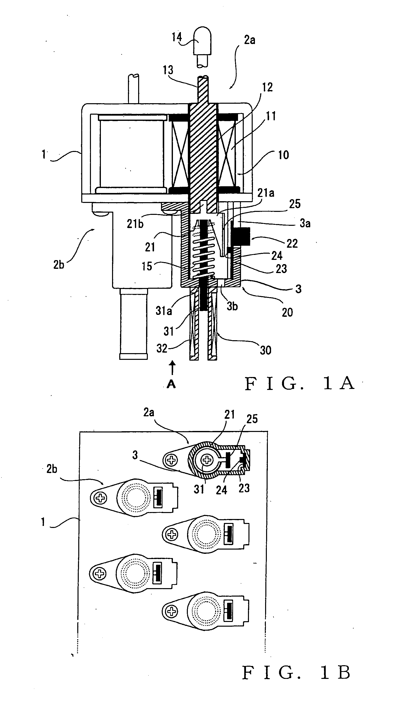
[0023]FIG. 1 is explanatory of an example construction of the first embodiment of the actuator unit, of which FIG. 1A is a partly-sectional side view of the actuator unit and FIG. 1B is a bottom end view of the actuator unit taken in a direction of arrow A of FIG. 1A. Specifically, FIG. 1 shows an actuator unit assembly having a plurality of the actuator units 2a, 2b, . . . held in place by a common (or same) yoke 1. The actuator units 2a, 2b, . . . provided, for example, in corresponding relation to keys of a keyboard musical instrument (not shown), such as a piano, and these actuator units 2a, 2b, . . . are used to impart a desired touch (i.e., reactive force / force sense) to key operation by a human player. The actuator units 2a, 2b, . . . are constructed identically, and in FIG...

second embodiment

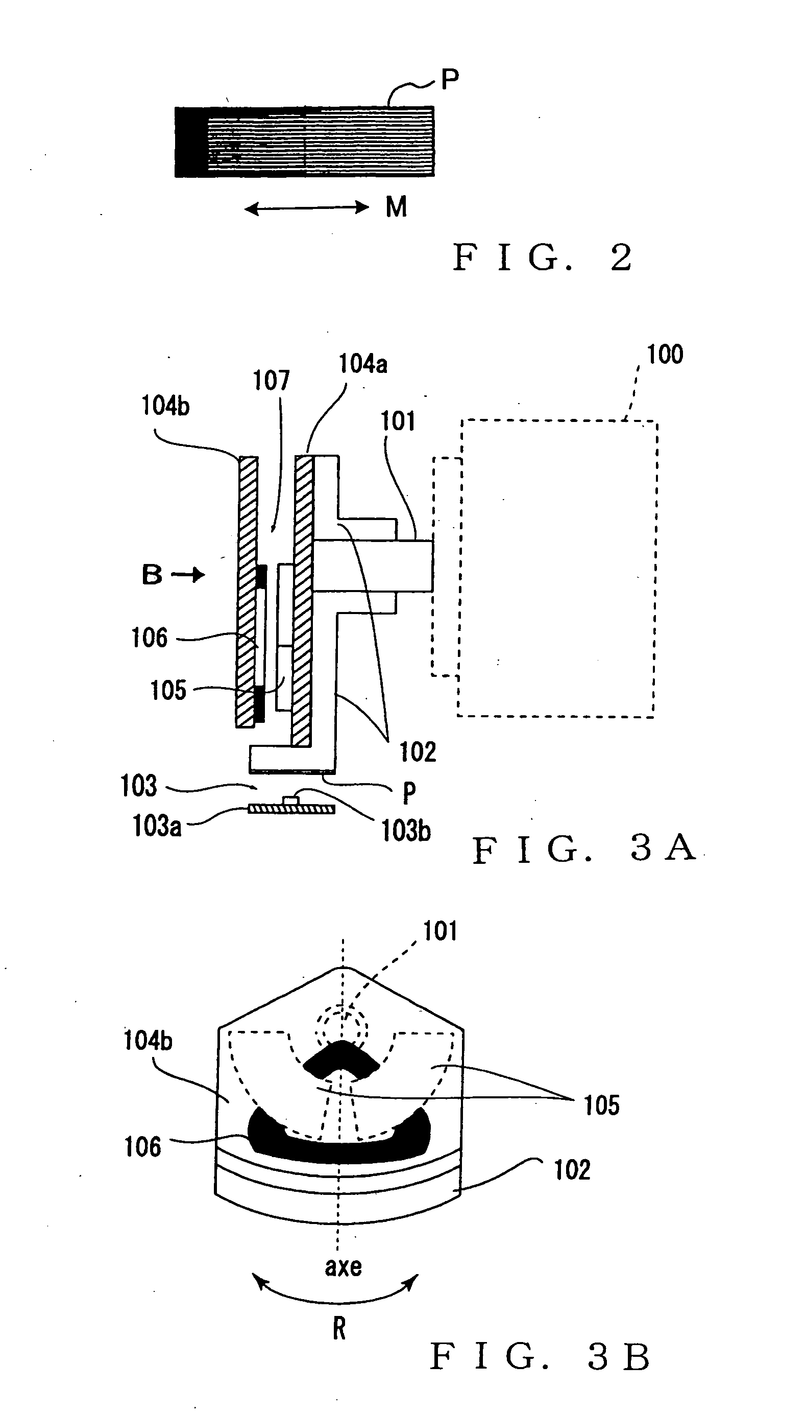
[0041] The embodiment has so far been described above in relation to the case in which the actuator section 10 is of the type where the plunger 12 moves linearly. FIG. 3A is a view showing another structural example (i.e., second embodiment) of the actuator unit of the present invention where the sensors are constructed as a unit; more specifically, FIG. 3A is a sectional view explanatory of the actuator unit where a position sensor and velocity sensor are provided as a unit on an actuator that is driven to rotate (rotary actuator).

[0042] Rotary motor (i.e., rotary actuator) 100 causes a rotation base 102, coupled via a rotation shaft 101 to the motor 100, to rotate (swing) in two directions within a predetermined rotational angular range. The rotation base 102 has an optical density pattern (gray scale) P on its outer peripheral portion. The optical density pattern P is similar to that shown in FIG. 2 and provided to cover the predetermined rotational angular range within which the...

third embodiment

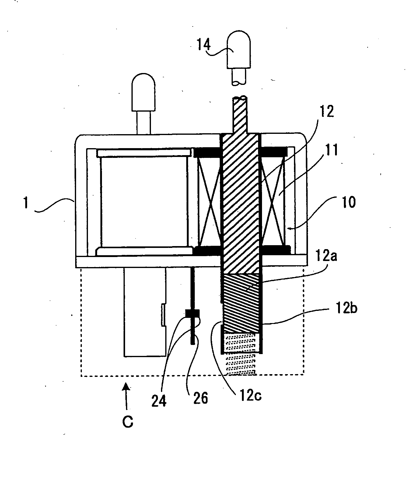
[0051]FIG. 5A is a view showing another structural example of the actuator unit provided with the light-reflection type sensor, and FIG. 5B is a schematic plan view taken in a direction of arrow C of FIG. 5A. In this example, a predetermined optical density pattern (gray scale), similar to the one shown in FIG. 2, is formed directly on a substantially entire peripheral surface of a bar 12a extending coaxially with and from the lower end of the plunger 12. The bar 12a is a cylindrical member formed of resin, such as PBT (Polybutylene Terephthalate resin) and having generally the same diameter as the plunger 12. Bobbin 12b, surrounding the plunger 12 and bar 12a, has an open window 12c in a predetermined position thereof that should oppose the sensor chip 24, and the sensor chip 24 is disposed on a surface of the sensor substrate 26 opposing the open window 12c. Because the optical density pattern is formed on the entire outer peripheral surface of the bar 12a, the pattern will never ...


PUM


Abstract

An actuator unit includes: a performance operator drive device including a movable member that mechanically drives the performance operator member; an optical pattern having a pattern to cause an amount of light reflection or light transmission to gradually vary in accordance with movement of the movable member; and an optical sensor that irradiates light toward the optical pattern and receives light reflected from or transmitted through the optical pattern. One of the optical pattern and the optical sensor is provided to move in interlocked relation to the movable member, and the amount of the reflected light or transmitted light, based on the optical pattern, is detected by the optical sensor, so that a moving position of the movable member is detected on the basis of the detected amount of the reflected or transmitted light.

Description

BACKGROUND OF THE INVENTION [0001] The present invention relates to an improved actuator unit suitable for use with a performance operator member, such as a key of a piano, a keyboard musical instrument provided with such an actuator unit, and an actuator unit assembly composed of a plurality of the actuator units. [0002] In the so-called automatic player pianos, keys of a keyboard musical instrument, such as a piano, are automatically operated to execute an unattended musical performance. Such automatic player pianos are arranged to selectively drive a plurality of key drive devices, provided in corresponding relation to the keys, on the basis of automatic performance information to be performed. Japanese Patent Application Laid-open Publication No. HEI-5-28195 discloses an example of a conventionally-known key drive device (i.e., actuator) for an automatic player piano. According to the disclosure in the No. HEI-5-28195 publication, the actuator in the form of an electromagnetic s...

Claims


Application Information

Patent Timeline
IPC IPC(8): G10F1/02G10H1/055G10H1/32G10H1/34G11B7/00H01F7/16
CPCG10H1/0553G10H2220/305G10H1/344
Inventor MURAMATSU, SHIGERU
Owner YAMAHA CORP
Why Eureka
Try Eureka