Fuel cell and fuel cell stack

Inactive Publication Date: 2005-06-30
HONDA MOTOR CO LTD
View PDF7 Cites 32 Cited by
  • Summary
  • Abstract
  • Description
  • Claims
  • Application Information

AI Technical Summary

Benefits of technology

[0009] A general object of the present invention is to provide a fuel cell having a simple and compact structure in whi

Problems solved by technology

Therefore, the fuel cell cannot be used in wide applications.
Further, since it is necessary to maintain the sealing performance for preventing the leak

Method used


Image

  • Fuel cell and fuel cell stack
  • Fuel cell and fuel cell stack
  • Fuel cell and fuel cell stack

Examples


Example

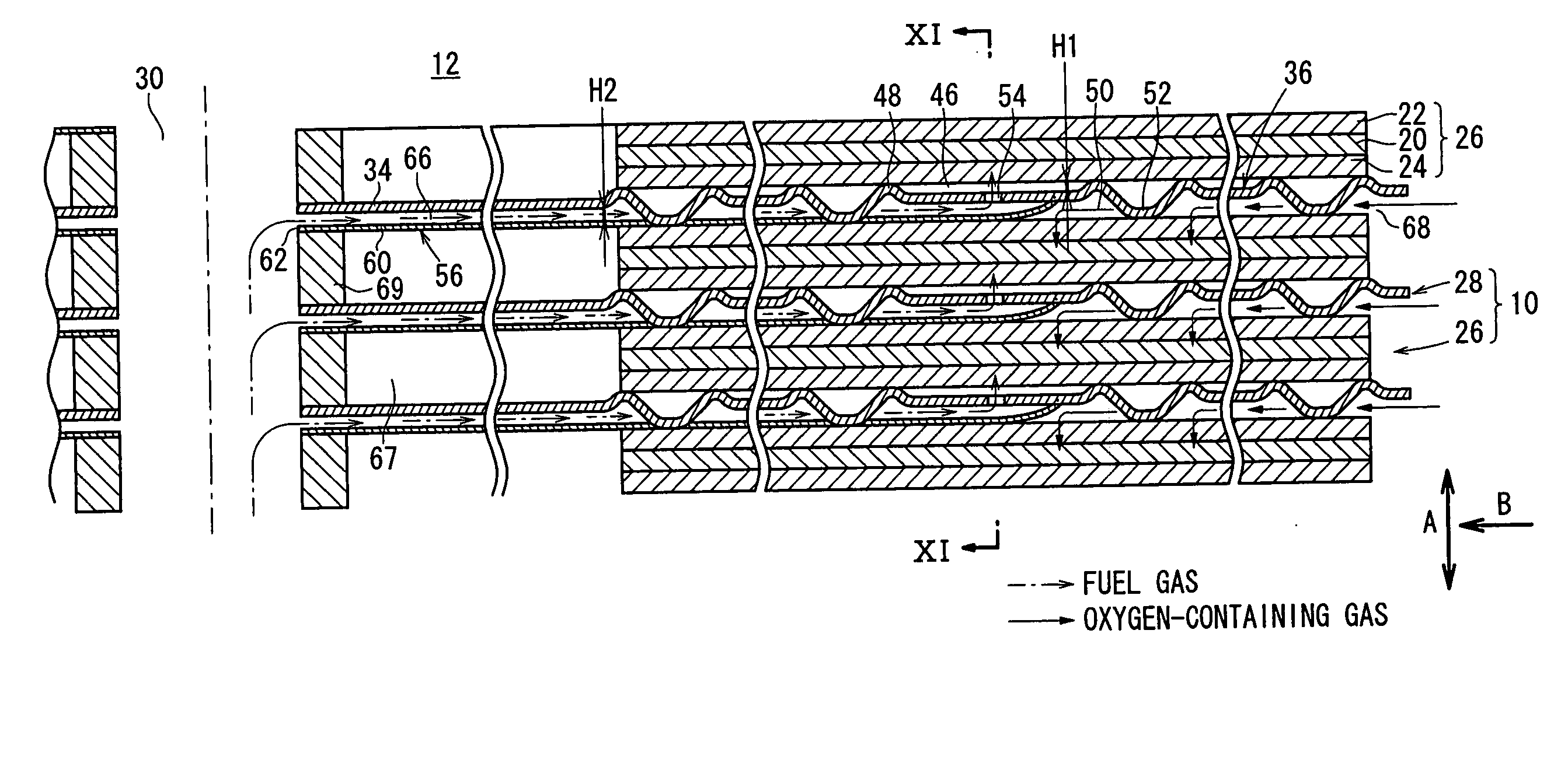
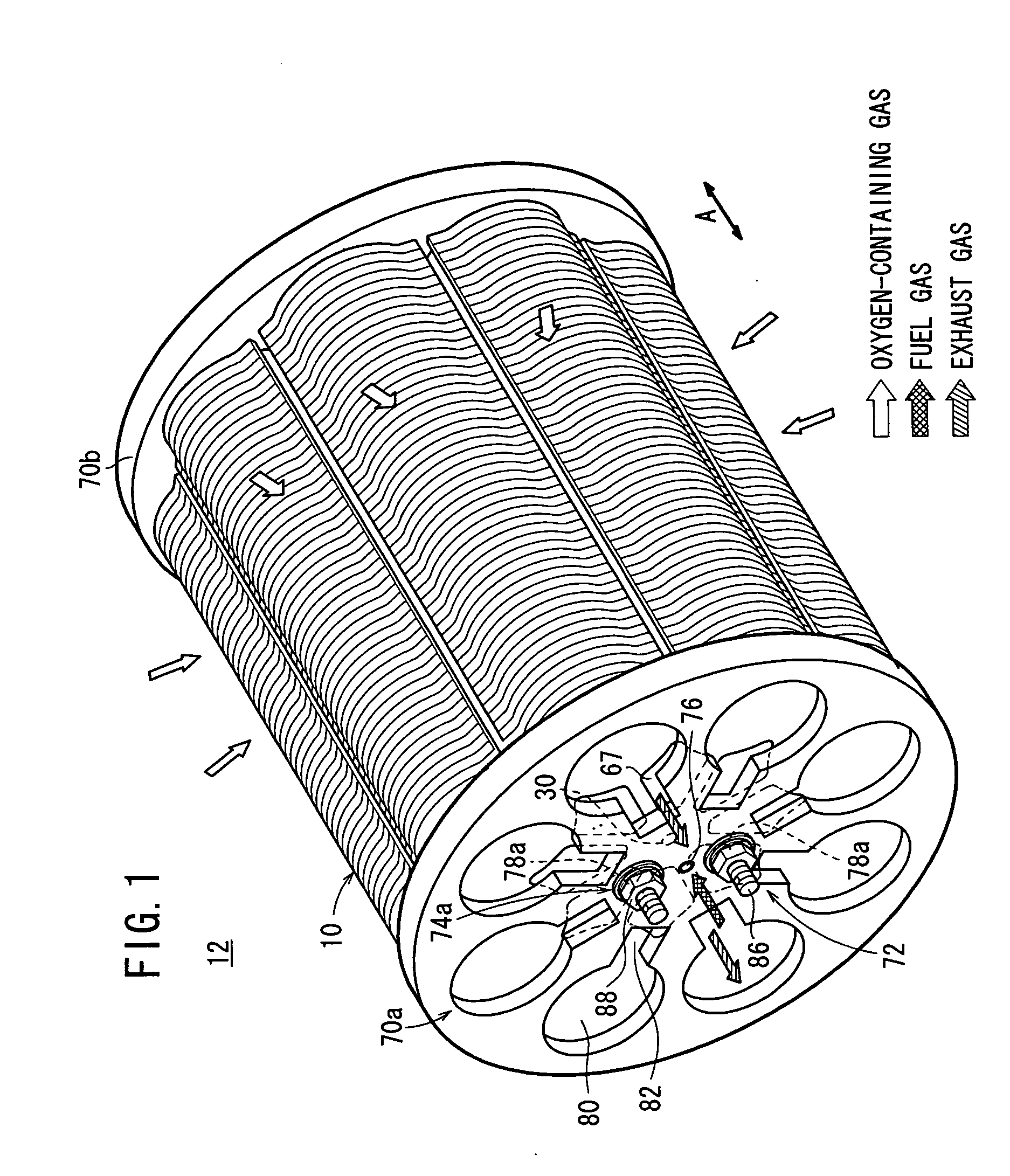
[0080] In the first embodiment, the separator 28 is a single plate, and the first and second protrusions 48, 52 are provided on both surfaces 36a, 36b of each of the circular disks 36 of the separator 28. The first protrusions 48 contact the anode 24, and the second protrusions 52 contact the cathode 22. The channel member 56 is fixed to the separator 28. The channel member 56 forms the fuel gas supply channels 66 connecting the fuel gas supply passage 30 and the fuel gas flow fields 46 through the fuel gas inlets 54.

[0081] Therefore, the oxygen-containing gas flows from the outer region to the central region of the fuel cell 10 in one direction indicated by the arrow B, and the fuel gas flows from the central region of the anode 24 to the outer circumferential region of the anode 24. Thus, not only is the dimension in the stacking direction of the separator 28 (thickness) significantly reduced, but also the fuel gas is uniformly distributed (supplied) to the entire electrode surfa...

Example

[0092] In the second embodiment of the present invention, the fuel gas supplied to the fuel gas supply passage 30 flows along the fuel gas supply channels 66 between the separator 28 and the channel member 124. Then, the fuel gas flows toward the anodes 24 through the fuel gas inlets 128 formed at the tip ends of the channel member 124.

[0093] Therefore, the fuel gas is supplied suitably and uniformly from the central region of the anode 24 to the outer circumferential region of the anode 24, and improvement in the power reaction efficiency is achieved advantageously. Further, it is not necessary to provide the fuel gas inlets 54 in the circular disks 36 in each of the separators 28. Therefore, the separators 28 have the simple structure, and reduction in the production cost is achieved easily.

[0094] In the first and second embodiments, as shown in FIG. 7, the first protrusion 48 has a ring shape perfectly circular (annular shape). Alternatively, for example, as shown in FIG. 15, t...


PUM


Abstract

A fuel cell includes an electrolyte electrode assembly and a pair of separators sandwiching the electrolyte electrode assembly. Each of the separators is a single plate, and includes a plurality of circular disks. First protrusions and second protrusions are provided on both surfaces of the circular disk. The first protrusions contact the anode of the electrolyte electrode assembly, and the second protrusions contact the cathode of the electrolyte electrode assembly. A channel member is provided on a surface of the separator facing the cathode. The channel member forms a plurality of fuel gas supply channels connected between a fuel gas supply passage and a fuel gas inlet for supplying a fuel gas into a fuel gas flow field.

Description

BACKGROUND OF THE INVENTION [0001] 1. Field of the Invention [0002] The present invention relates to a fuel cell including an electrolyte electrode assembly and a pair of separators sandwiching the electrolyte electrode assembly. The electrolyte electrode assembly includes an anode, a cathode, and an electrolyte interposed between the anode and the cathode. Each of the separators is a single plate. Further, the present invention relates to a fuel cell stack formed by staking a plurality of fuel cells. [0003] 2. Description of the Related Art [0004] Typically, a solid oxide fuel cell (SOFC) employs an electrolyte of ion-conductive solid oxide such as stabilized zirconia. The electrolyte is interposed between an anode and a cathode to form an electrolyte electrode assembly (unit cell). The electrolyte electrode assembly is interposed between separators (bipolar plates). In use, a predetermined numbers of the unit cells and the separators are stacked together to form a fuel cell stack....

Claims


Application Information

Patent Timeline
IPC IPC(8): H01M8/02H01M8/12H01M8/24
CPCH01M8/0254H01M8/0258H01M8/2425Y02E60/525H01M8/248H01M2008/1293Y02E60/50H01M8/2475H01M8/026H01M8/2432H01M8/2457H01M8/2483H01M8/02H01M8/04H01M8/24
Inventor HOMMA, HIROKIIZUMI, MASAHIKODAN, KOJI
Owner HONDA MOTOR CO LTD
Why Eureka
Try Eureka