

Fuel cell can fuel cell stack
- Summary
- Abstract
- Description
- Claims
- Application Information
AI Technical Summary
Benefits of technology
Problems solved by technology
Method used
Image

Examples
first embodiment
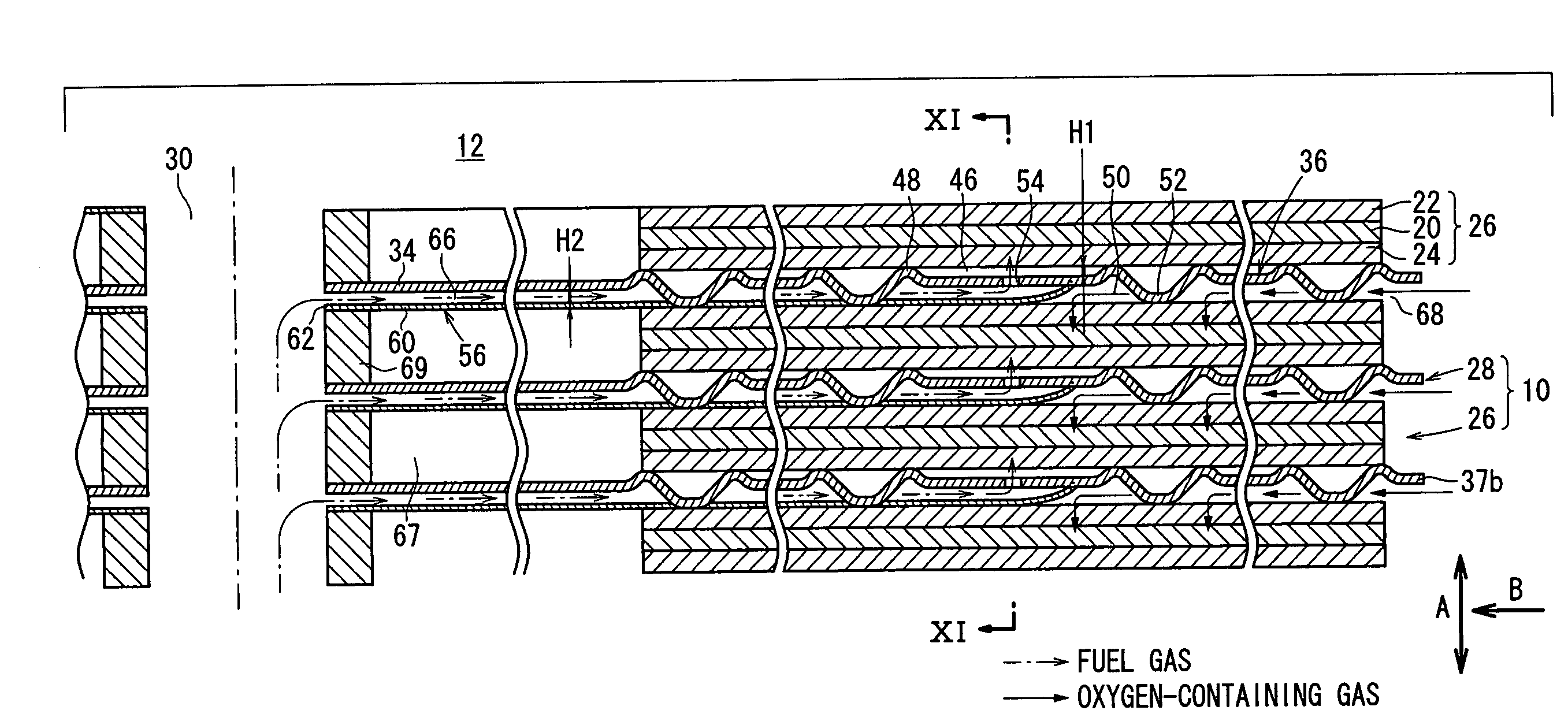
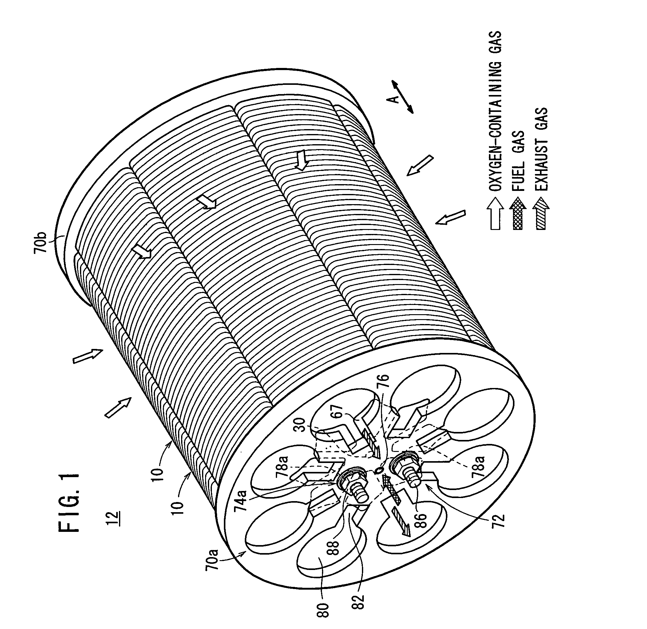
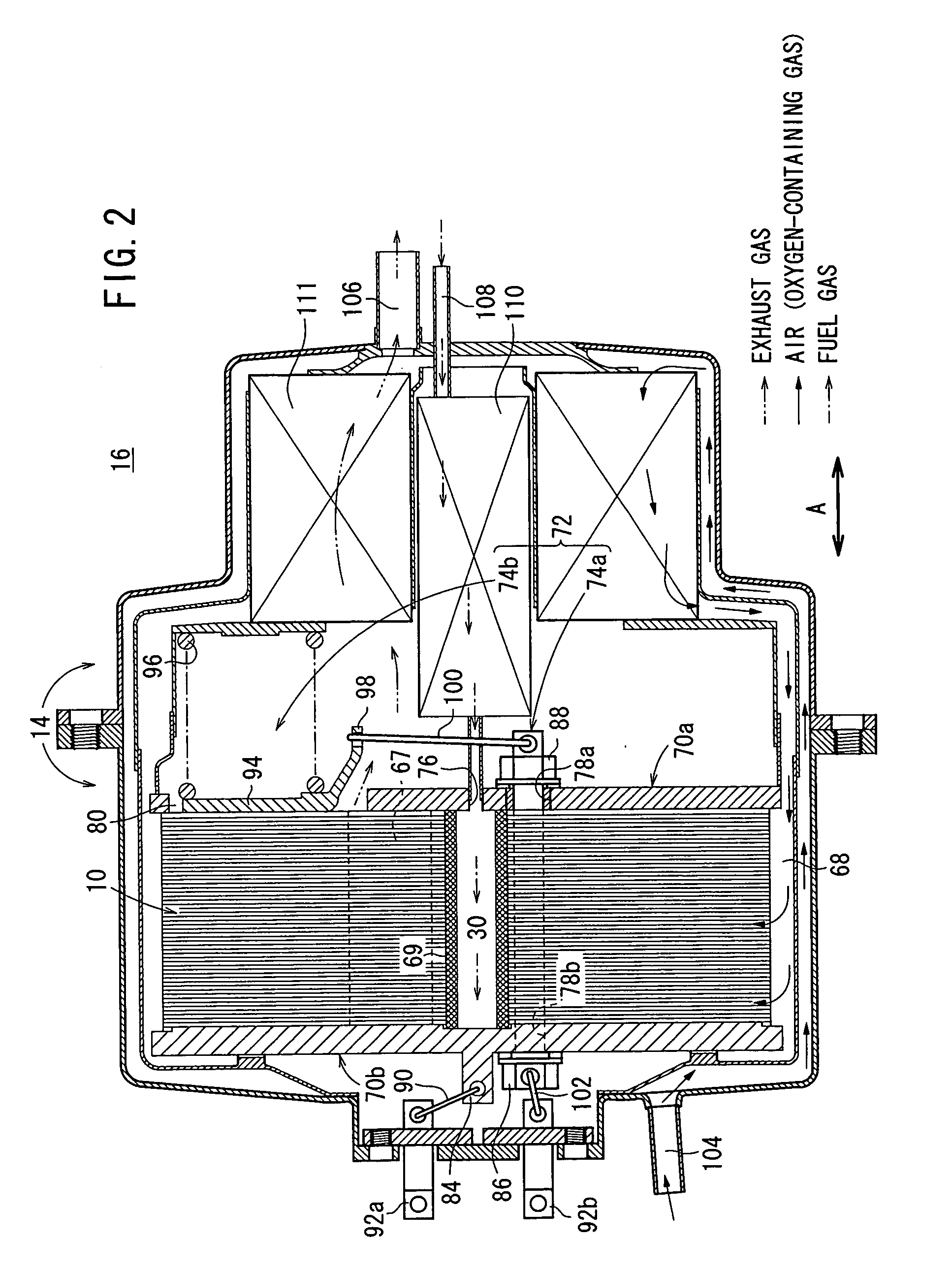
[0046]FIG. 1 is a perspective view schematically showing a fuel cell stack 12 formed by stacking a plurality of fuel cells 10 according to the present invention indicated by an arrow A. FIG. 2 is a cross sectional view showing part of a fuel cell system 16 in which the fuel cell stack 12 is disposed in a casing 14.
[0047] The fuel cell 10 is a solid oxide fuel cell (SOFC) used in various applications, including stationary and mobile applications. As shown in FIGS. 3 and 4, the fuel cell 10 includes electrolyte electrode assemblies 26. Each of the electrolyte electrode assemblies 26 includes a cathode 22, an anode 24, and an electrolyte (electrolyte plate) 20 interposed between the cathode 22 and the anode 24. For example, the electrolyte 20 is made of ion-conductive solid oxide such as stabilized zirconia. Each of the electrolyte electrode assemblies 26 has a substantially trapezoidal shape which is formed by dividing a substantially ring body at certain angles. The electrolyte elect...
second embodiment
[0094] In the present invention, the fuel gas supplied to the fuel gas supply passage 30 flows along the fuel gas supply channels 66 between the separator 28 and the channel member 124. Then, the fuel gas flows toward the anodes 24 through the fuel gas inlets 128 formed at the tip ends of the channel member 124.
[0095] Therefore, the fuel gas is supplied suitably and uniformly from the central region of the anode 24 to the outer circumferential region of the anode 24, and improvement in the power reaction efficiency is achieved advantageously. Further, it is not necessary to provide the fuel gas inlets 54 in the trapezoidal portions 36 in each of the separators 28. Therefore, the separators 28 have the simple structure, and reduction in the production cost is achieved easily.
[0096] In the first and second embodiments, as shown in FIG. 7, the first protrusion 48 has a ring shape perfectly circular (annular shape). Alternatively, for example, as shown in FIG. 15, the first protrusion ...
PUM
 Abstract
Description
Claims
Application Information