Communication resource management device

Inactive Publication Date: 2005-06-30
FUJITSU LTD
View PDF11 Cites 24 Cited by
  • Summary
  • Abstract
  • Description
  • Claims
  • Application Information

AI Technical Summary

Benefits of technology

[0011] A general object of the present invention is to provide an improved and useful communicati

Problems solved by technology

However, even within the same mobile communication system, the transfer capacity and/or traffic volume required for the control channel are not always the same.
Thus, conventional techniques such as mentioned above include problems in that it is impossible to flexibly handle such a communication condition.
However, when the transfer rate is improved in the aforementioned manner, since the transmission bands allocated in a fixed manner are increased among the avail

Method used


Image

  • Communication resource management device
  • Communication resource management device
  • Communication resource management device

Examples


first embodiment

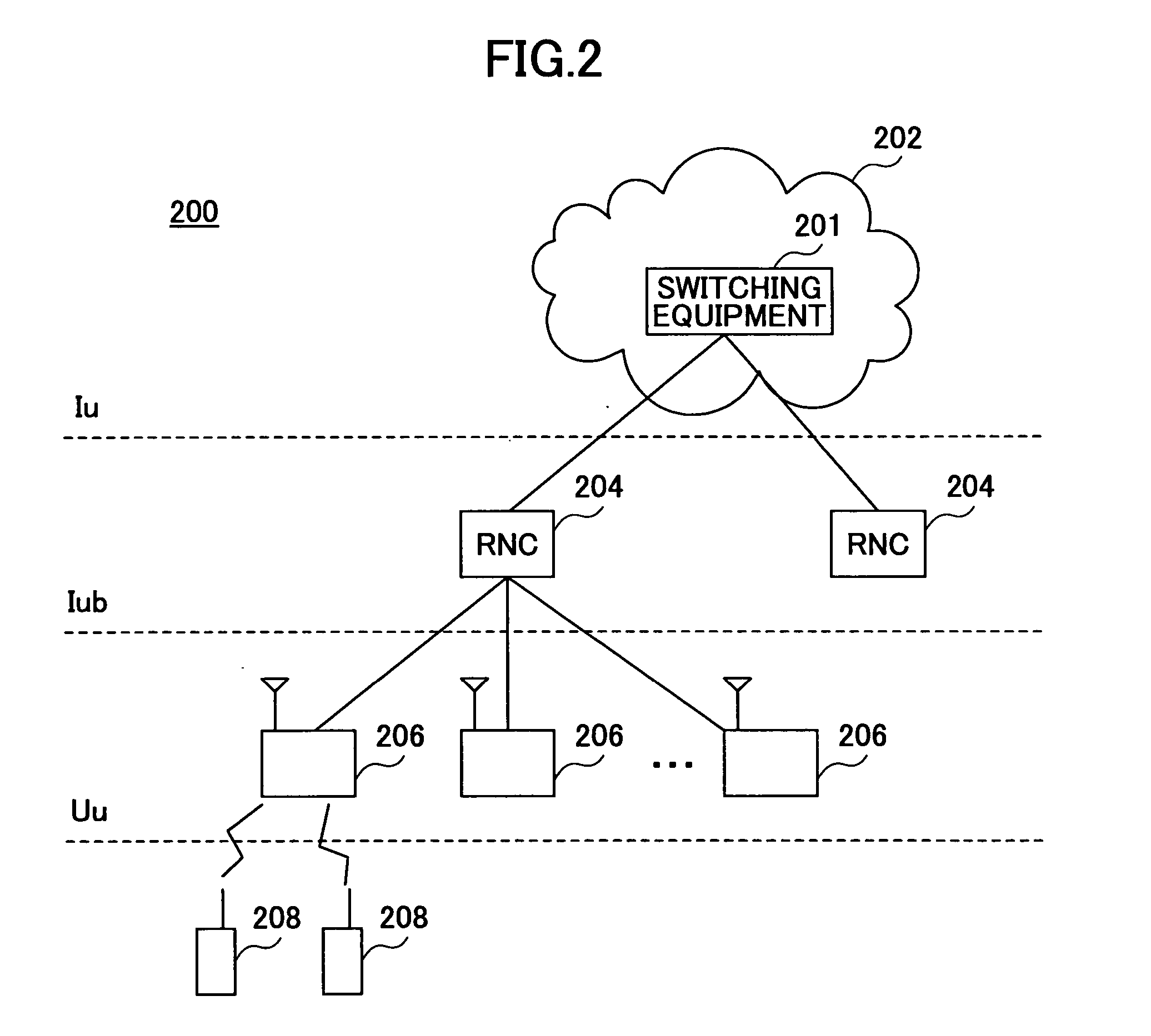
[0026]FIG. 2 is a schematic diagram of a mobile communication system 200 to which the present invention may be applied. The mobile communication system 200 is, for example, a CDMA communication system based on the specification of the 3GPP. The mobile communication system 200 includes a network 202 such as the Internet, and the network 202 is provided with switching equipment 201 for establishing a connection with another communication system such as a fixed telephone network. The mobile communication system 200 includes radio network controllers (RNCs) 204 connected to the network 202. Each radio network controller 204 controls plural wireless base stations 206 connected thereto. Each of the wireless base stations 206 performs radio communications with a mobile terminal 208 that belongs to its own region (cell). Allocation of communication resources such as the transmission bands (transfer rates) for mobile phones is managed by the radio network controller 204. In FIG. 2, Iu indica...

second embodiment

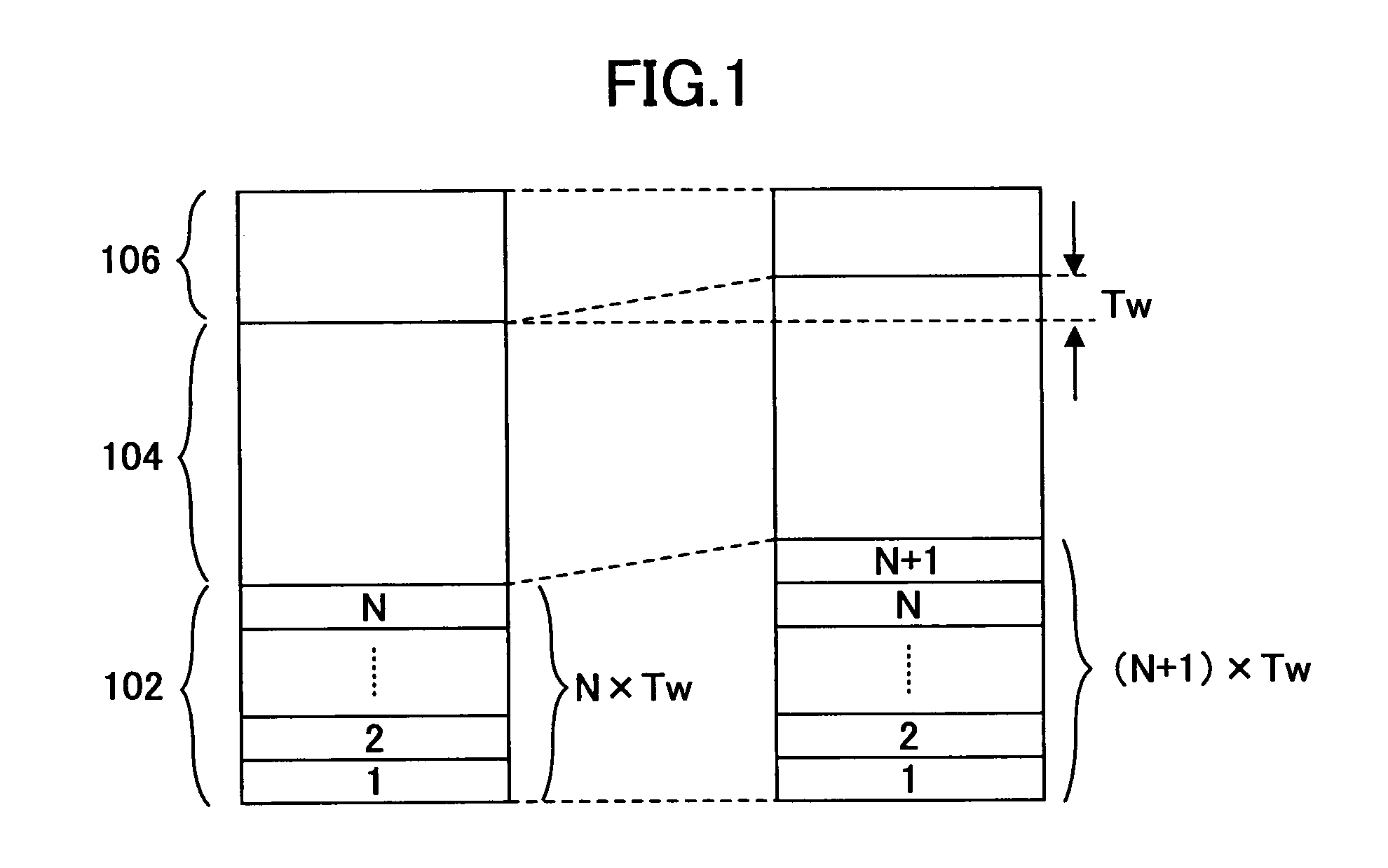
[0052] Data transfer from a transmitting node to a receiving node is performed such that a signal of a predetermined data size, such as 1 block or 2 blocks, is transferred at predetermined transmission time intervals (TTI) such as 10 ms or 40 ms. Generally, the format of a signal transmitted from and received by a radio network controller (RNC) is as shown in FIG. 8 and includes a header 802 and a subsequent payload 804. The payload 804 includes transmission blocks 1, 2, 3, . . . to be transferred. The header 802 includes a transport format indicator (TFI), which indicates the number or amount of the transmission blocks (TB) following the header. Although an actual TFI is a value related to the data amount of transmission blocks, the actual TFI is not always a numeric value directly representing the number of transmission blocks. However, for convenience of explanation, it is assumed that a TFI directly represents the number of transmission blocks. For example, when TFI=3, then 3 tr...


PUM


Abstract

A communication resource management device changes the transfer rate of a first control channel related to a first mobile terminal according to a communication condition. The device determines whether there is a frequency band for which it is not determined whether the frequency band is to be used in a predetermined time period based on a current transfer rate of a second control channel related to a second mobile terminal and an amount of data to be transmitted in the second control channel; and allocates, to the first mobile terminal, at least a part of the frequency band for the second control channel with respect to the second mobile terminal in a predetermined period of time. The device changes the transfer rate in the first control channel while maintaining the total frequency band for plural control channels related to plural mobile terminals at a constant value.

Description

CROSS-REFERENCE TO RELATED APPLICATION [0001] This application is a U.S. continuation application, filed under 35 USC 111(a) and claiming the benefit under 35 USC 120 and 365(c), of PCT application JP2003 / 000602, filed Jan. 23, 2003. The foregoing application is hereby incorporated herein by reference.BACKGROUND OF THE INVENTION [0002] 1. Field of the Invention [0003] The present invention generally relates to devices for managing communication resources, and more particularly, to a communication resource management device for varying the transfer rate of a control channel. [0004] 2. Description of the Related Art [0005] A user of a mobile terminal in a mobile communication system can communicate with a desired party by using a communication channel (or information channel) that is set for each call. Setting and management of the communication channel are performed via a control channel. In this case, the data transfer capacity required for the control channel generally differs for ...

Claims


Application Information

Patent Timeline
IPC IPC(8): H04B7/26H04L29/08H04W16/02H04W16/10H04W28/00H04W28/06H04W28/12H04W28/18H04W28/20H04W28/22H04W36/16H04W72/04H04W76/02H04W76/04H04W84/12H04W88/12H04W92/12
CPCH04W28/06H04W28/12H04W28/20H04W92/12H04W36/16H04W76/04H04W88/12H04W28/22H04W76/20
Inventor SHINOZAKI, ATSUSHI
Owner FUJITSU LTD
Why Eureka
Try Eureka