Method and apparatus for controlling humidity and mold

Inactive Publication Date: 2005-07-07
DRYAIR 2000
12 Cites 30 Cited by

AI-Extracted Technical Summary

Problems solved by technology

It is well known that excessive moisture in buildings causes considerable problems.
Drywall and flooring absorb moisture and are readily damaged if the excessive moisture condition persists for any length of time.
Furthermore, mold begins to form on the damp building materials, and can remain in the structure even after it has dried, causing breathing problems for persons occupying the building.
The methods were slow and allowed mold to form on the interior framing, which could then go unnoticed and be covered up and then later present a health hazard to occupants.
While flooded buildings demonstrate an extreme situation, excessive moisture also causes probl...

Method used

[0036] Raising the temp of air 10° C. will reduce the relative humidity of the air by about 50%. By sensing the relative humidity of the air at a sensing location 19A at the outlet 13 of the air stream 9 the heat controller 17 can be operated to supply heat at the proper rate to achieve the desired relative humidity in the air stream 9, and thus in the enclosed space 3.
[0043] The heat exchanger unit 105 includes coarse filters 39, 41 located upstream from the HEPA filter 37 such that the air stream passes through the coarse filters 39, 41 and is pre-filtered prior to passing through the HEPA filter 37. A typical pre-filtration process could be in two stages whereby the air stream 9 first passes through a rough, “loose-media” filter 39 followed by a pleated filter 41 with a MERV (minimum efficiency reporting value) of “8” by ASHRAE Standard 52.2. By changing the coarse filters 39, 41 regularly, the life of the more costly HEPA filter 37 can be prolonged.
[0046] Thus the heat exchanger unit 105 has the capability of scrubbing as well as heating or cooling the intake air. The HEPA filter 37 will remove a very high percentage of mold spores, bacteria, and other undesirable particles. In contrast to the prior art systems for drying flooded buildings which controlled mold only by drying very quickly, the apparatus of the present invention can be used to dry at a controlled rate to reduce damage to sensitive materials...

Benefits of technology

[0026] In hot climates, it would be possible to dry building interiors under construction after hours when they are unoccupied by introducing a heated air stream with reduced relative humidity compared to that of the atmosphere. By drying the interior overnight, an...

Abstract

A apparatus for reducing a relative humidity of air inside an enclosed space comprises a portable outside air heat exchanger unit comprising a fan operative to create an air stream by drawing outside air from an intake and discharging the air stream through an outlet inside the enclosed space, and a temperature adjusting element located in the air stream. A heating source supplies heat energy to the temperature adjusting element in response to directions from a heat controller. A humidity sensor is operative to sense the relative humidity of the air in a sensing location and to send a humidity signal to the heat controller to change the amount of heat energy supplied to the temperature adjusting element in response to the humidity signal. HEPA filters and ultra-violet lights can shine on the air stream to kill mold spores and the like.

Application Domain

Technology Topic

Violet lightAirflow +10

Image

  • Method and apparatus for controlling humidity and mold
  • Method and apparatus for controlling humidity and mold
  • Method and apparatus for controlling humidity and mold

Examples

  • Experimental program(1)

Example

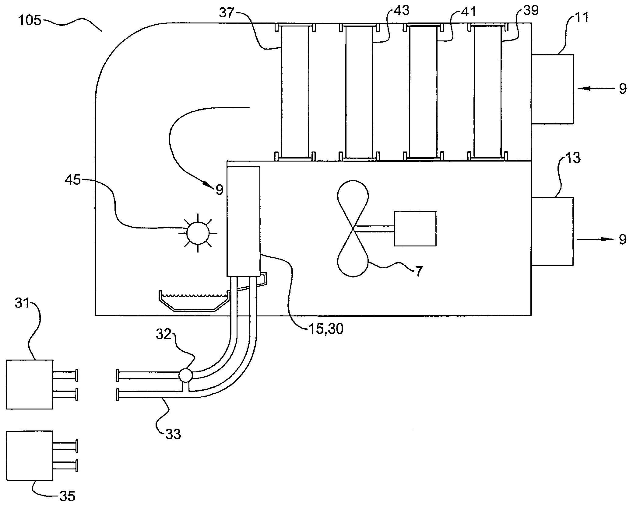
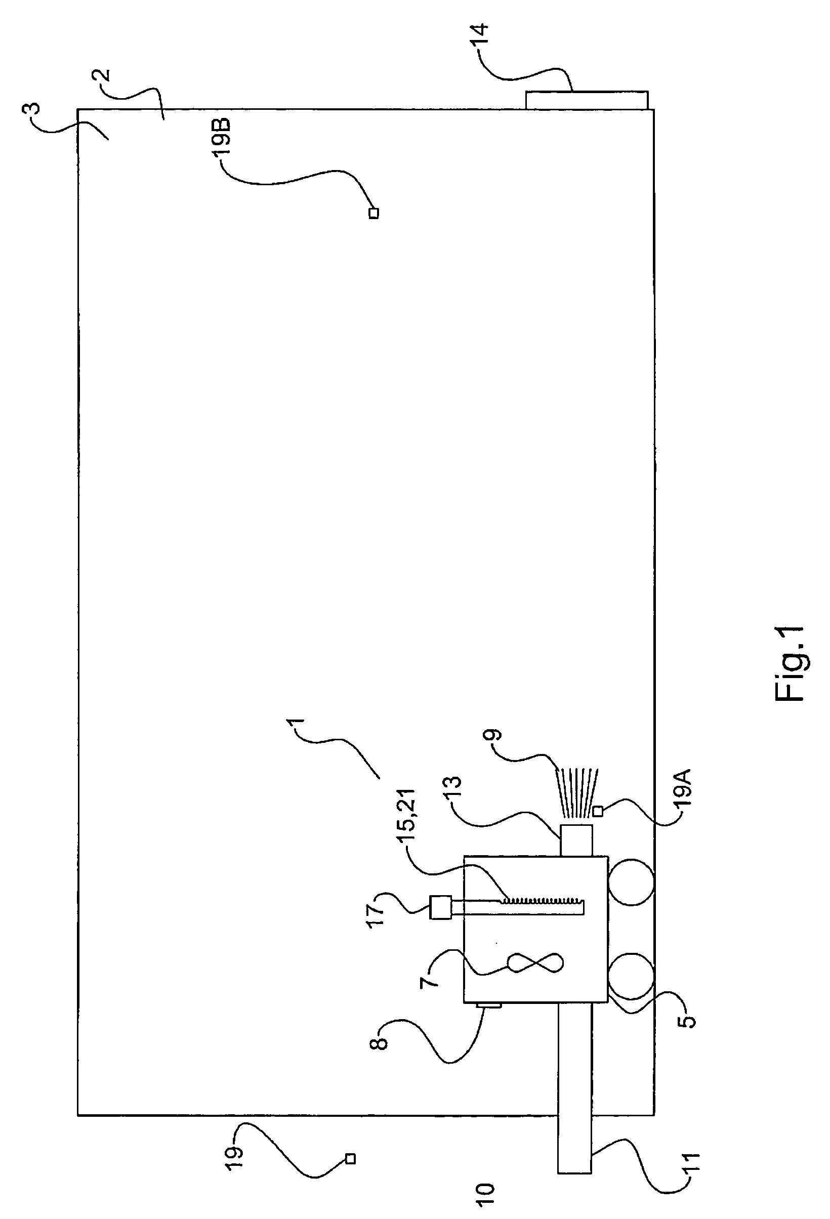
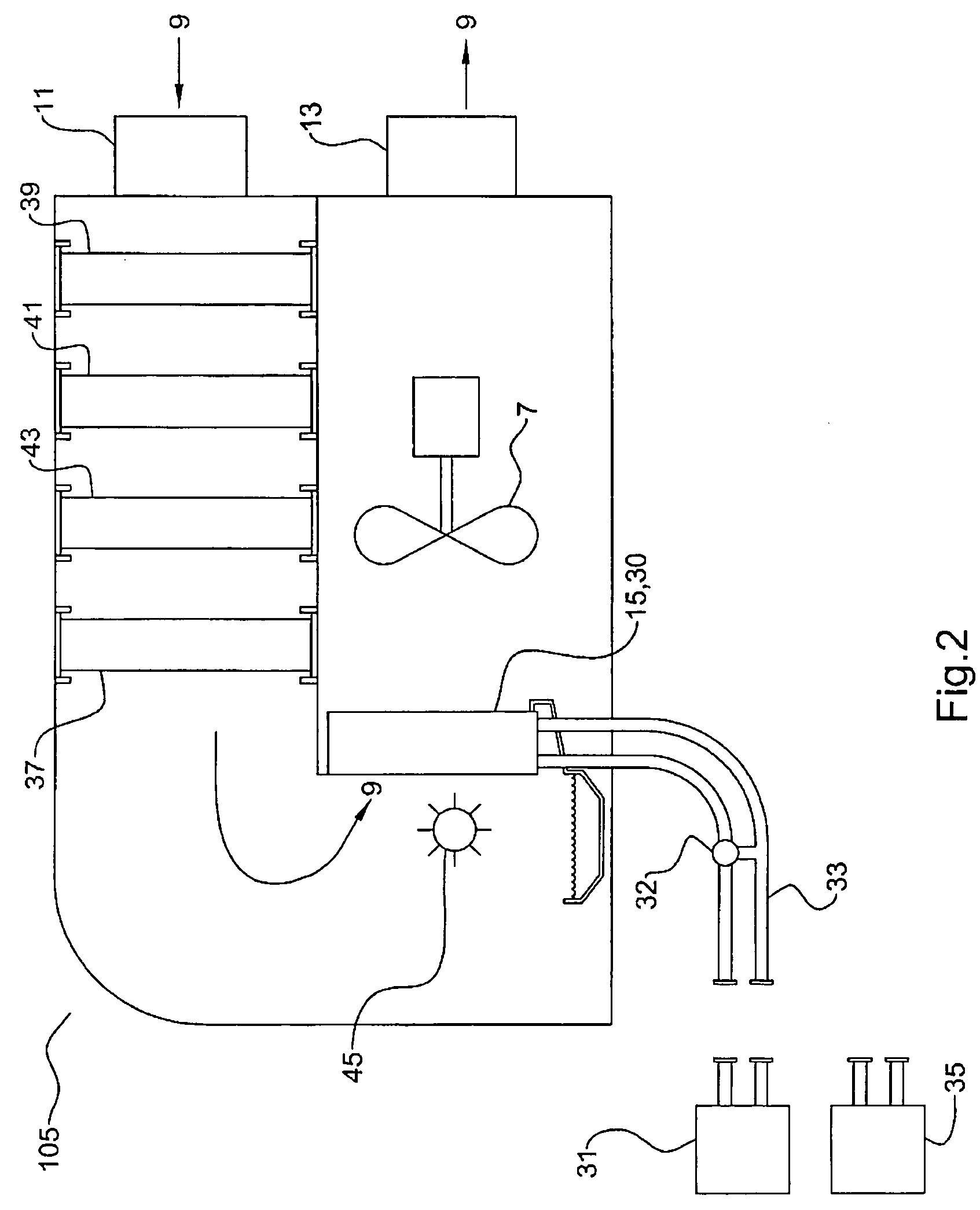
[0033]FIG. 1 schematically illustrates an apparatus 1 for reducing a relative humidity of inside air 2 inside an enclosed space 3. The apparatus 1 comprises a portable outside air heat exchanger unit 5 comprising a fan 7 operative to create an air stream 9 by drawing air from an intake 11 and discharging the air through an outlet 13. The intake 11 is adapted to draw outside air 10 from outside the enclosed space 3 and the outlet 13 is adapted to discharge the air stream 9 into the enclosed space 3. The outside air heat exchanger unit 5 is illustrated located inside the enclosed space 3, with the intake 11 located outside, however alternatively the outside air heat exchanger unit 5 could be located outside with the outlet 13 located inside the enclosed space 3. Portability is provided by wheels or the like as illustrated.
[0034] The outside air heat exchanger unit 5 further comprises a temperature adjusting element 15 located in the air stream 9. A heating source is connectable to the heat exchanger unit 5 to supply heat energy to the temperature adjusting element 15 in response to directions from a heat controller 17. A humidity sensor 19 is operative to sense the relative humidity of the air in a sensing location and to send a humidity signal to the heat controller 17 through a signal line, wireless connection, or the like. The heat controller 17 is operative to receive the humidity signal and change the amount of heat energy supplied to the temperature adjusting element 15 in response to the humidity signal.
[0035] The sensing locations can be located to sense the relative humidity of the outside air, illustrated at 19, the relative humidity of the air stream 9, illustrated at 19A, or the relative humidity of the inside air 2 at a location remote from the air stream 19B.
[0036] Raising the temp of air 10° C. will reduce the relative humidity of the air by about 50%. By sensing the relative humidity of the air at a sensing location 19A at the outlet 13 of the air stream 9 the heat controller 17 can be operated to supply heat at the proper rate to achieve the desired relative humidity in the air stream 9, and thus in the enclosed space 3.
[0037] Alternatively, temperature sensors could be provided and the humidity and temperature could be sensed at the intake 11, and the temperature of the air stream 9 sensed at the outlet 13. The required adjustment in the amount of heat supplied could be calculated, given the relative humidity of the outside air 10 being drawn in, by determining the temperature rise required to achieve the desired relative humidity of the air stream 9 at the outlet.
[0038] Alternatively again the humidity can be sensed inside at the sensing location of the humidity sensor 19B. With just this measurement the temperature adjusting element 15 could initially operate at its maximum level with the result that the relative humidity of the air stream 9 could be very low initially and could damage sensitive materials adjacent to the outlet 13. In any event, sensing the relative humidity allows the apparatus 1 to operate to reduce the relative humidity of the inside air 2 in the enclosed space 3
[0039] In the embodiment of FIG. 1, the temperature adjusting element 15 comprises an electric heating element 21 and the heating source is an electrical power outlet connectable to the electric element by a power cord in a conventional manner. The apparatus 1 includes a fan controller 8 operative to change the speed of the fan 7 to vary the volume of air in the air stream 9. The fan controller can be manually controlled, or connected to receive the humidity signal, temperature signals or the like and programmed to vary the fan speed in response to information received. Thus both the volume and relative humidity of the air stream 9 can be varied in response to the humidity signal. Where drying is required it will be desired to move large volumes of dryer air into the enclosed space 3 and thus push similar volumes of wetter air out through an exhaust port 14, which could be a door, window, or the like. Where considerable drying is not required, and it is necessary to just maintain the relative humidity in the enclosed space 3, the volume of outside air drawn in can be reduced.
[0040]FIG. 2 illustrates an alternate embodiment of a heat exchanger unit 105 wherein the temperature adjusting element 15 comprises a fluid coil 30 and wherein the heating source is a fluid heater 31 connectable to the fluid coil 30 by conduits 33 such that heated fluid flows from the fluid heater 31 through the fluid coil 30 and back to the fluid heater 31. The fluid heater 31 could conveniently be a boiler system set up at a central location outside so that combustion in the system does not affect the inside air. The boiler system could be made connectable to a plurality of heat exchanger units.
[0041] A fluid cooler 35 using refrigerant or the like to cool the fluid could also be provided that was in a similar manner connectable to the fluid coil 30 by conduits 33 such that cooled fluid flows from the fluid cooler 35 through the fluid coil 30 and back to the fluid cooler 35 in response to directions from a cooling controller. Thus the fluid coil 30 illustrated can be connected to heat or cool the air entering the intake 11. The flow of heated or cooled fluid through the fluid coil 30 is controlled by a heat controller 32 that can be operated manually, or that can control the flow in response to signals from humidity, temperature, an like sensors.
[0042] The heat exchanger unit 105 includes a HEPA filter 37 capable of High Efficient Particulate Attenuation located such that the air stream 9 passes through the HEPA filter 37. Suitable filters are capable of removing 99.97% of mold or any other air borne particles as small as 0.3 microns in diameter at the rated airflow. Manufacturers of certified HEPA filters will list the maximum design airflow for each size they offer. For example one available 24″×12″×12″ filter is rated for a maximum of 855 cubic feet per minute (cfm), and a 24″×24″×12″ filter is rated for a maximum of 1900 cfm.
[0043] The heat exchanger unit 105 includes coarse filters 39, 41 located upstream from the HEPA filter 37 such that the air stream passes through the coarse filters 39, 41 and is pre-filtered prior to passing through the HEPA filter 37. A typical pre-filtration process could be in two stages whereby the air stream 9 first passes through a rough, “loose-media” filter 39 followed by a pleated filter 41 with a MERV (minimum efficiency reporting value) of “8” by ASHRAE Standard 52.2. By changing the coarse filters 39, 41 regularly, the life of the more costly HEPA filter 37 can be prolonged.
[0044] The heat exchanger unit 105 also includes an activated carbon filter 43 located upstream from the HEPA filter 37 such that the air stream passes through the activated carbon filter 43 prior to passing through the HEPA filter 37. Such activated carbon filters will adsorb most airborne gases and odours.
[0045] Yet further the illustrated heat exchanger unit 105 also includes an ultra-violet light 45 oriented to irradiate the air stream 9 after the air stream 9 has passed through the HEPA filter. The ultra-violet rays are able to kill a significant proportion of most typical bacteria. The ultra-violet light 45 in combination with the HEPA filter 37 removes a very high proportion of micro-organisms, spores, bacteria and the like, as well as other undesirable particles, from the air stream 9.
[0046] Thus the heat exchanger unit 105 has the capability of scrubbing as well as heating or cooling the intake air. The HEPA filter 37 will remove a very high percentage of mold spores, bacteria, and other undesirable particles. In contrast to the prior art systems for drying flooded buildings which controlled mold only by drying very quickly, the apparatus of the present invention can be used to dry at a controlled rate to reduce damage to sensitive materials, while at the same time removing mold spores from outside air drawn into the building, or from the inside air as well. In buildings under repair or construction, removing mold spores can greatly reduce the risk of mold forming and persisting after the building is occupied.
[0047] Use of the activated carbon filter 43 will also remove a high proportion of airborne fumes and odors, such as can be present due to carpet adhesive, paint, and like construction materials.
[0048] As illustrated in FIG. 3, a plurality of heat exchanger units 105 can be employed. Heat exchanger unit 105A is oriented with the intake 11 outside to draw in and heat outside air 10 to force wetter inside air 2 out of the enclosed space 3 through an exhaust port 14. Heat exchanger units 105B, 105C are oriented with the intake 11 inside to draw in inside air 2 to remove mold spores, and also to heat the inside air if desired. The outlets 13 on all heat exchanger units 105 are directed into the enclosed space 3.
[0049] In FIG. 3 all heat exchanger units 105 comprise a fluid coil supplied with heat from a single fluid heater 31. Heat exchanger units with electric heating elements could be used as well. Heat controls 32 operate in response to manual commands, or can be configured to respond to changes in humidity, temperature, and the like. For example the heat exchanger unit 105A could be controlled by a humidity signal from a humidity sensor 19 located in the enclosed space 3 thus controlling humidity in the enclosed space 3, and the heat exchanger units 105B, 105C could be controlled by a temperature sensor 50 to control the temperature in the enclosed space 3. A master controller can be provided to coordinate the operation of all or some of the heat exchanger units 105.
[0050] Thus the invention provides a method of reducing the relative humidity of the inside air 2 inside an enclosed space 3 comprising drawing outside air 10 from outside the enclosed space 3 to create an air stream 9 discharging into the enclosed space 3, and allowing an amount of air substantially corresponding to the air stream 9 to escape from the enclosed space 3; sensing the relative humidity of the air in at least one sensing location with a humidity sensor 19, and in response to the relative humidity sensed at the sensing location, raising the temperature of the outside air 10 drawn in as required to lower the relative humidity of the air stream 9 such that the relative humidity of the inside air 2 is substantially maintained at a desired relative humidity.
[0051] Further the air stream 9 can be purified or scrubbed by filtering the outside air with a HEPA filter 37 capable of High Efficient Particulate Attenuation to substantially remove mold spores and like bacteria and other airborne particles. In addition the method can comprise shining an ultra-violet light on the air stream to kill micro-organisms and spores in the air stream.
[0052] The foregoing is considered as illustrative only of the principles of the invention. Further, since numerous changes and modifications will readily occur to those skilled in the art, it is not desired to limit the invention to the exact construction and operation shown and described, and accordingly, all such suitable changes or modifications in structure or operation which may be resorted to are intended to fall within the scope of the claimed invention.

PUM

PropertyMeasurementUnit
Temperature
Volume
Speed
tensileMPa
Particle sizePa
strength10

Description & Claims & Application Information

We can also present the details of the Description, Claims and Application information to help users get a comprehensive understanding of the technical details of the patent, such as background art, summary of invention, brief description of drawings, description of embodiments, and other original content. On the other hand, users can also determine the specific scope of protection of the technology through the list of claims; as well as understand the changes in the life cycle of the technology with the presentation of the patent timeline. Login to view more.

Similar technology patents

Selective garbage screening and feeding device and method

InactiveCN102950109AReduce humidityFor subsequent sortingSievingScreeningCrankDrive motor
Owner:BEIJING HAOHAI TIANJI TECH +1

Swimming goggle

ActiveUS20190381361A1Optimal level of comfort and efficacyReduce humidityDetails involving processing stepsImage analysisEngineering
Owner:ADIDAS

Classification and recommendation of technical efficacy words

Why Eureka
Try Eureka