Apparatus and method for suppressing internal combustion ignition engine emissions

a technology of internal combustion engine and internal combustion engine, which is applied in the direction of electric control, speed sensing governor, machines/engines, etc., can solve the problems of insufficient air to support the complete combustion of the fuel, the fuel is later burned and subject to high temperatures, and the effect of reducing emissions

Active Publication Date: 2005-07-07
GE GLOBAL SOURCING LLC
View PDF10 Cites 17 Cited by
  • Summary
  • Abstract
  • Description
  • Claims
  • Application Information

AI Technical Summary

Benefits of technology

[0008] The disclosed method relates a method of reducing emissions from an internal combustion engine, the method comprising: retarding a fuel injection timing in at least one piston cylinder when the internal combustion engine is in a transient mode.

Problems solved by technology

One cause of this phenomenon is incomplete fuel-air mixing during the injection and combustion of the fuel injected in compression cylinders during these acceleration and load ascending transient engine operating modes.
As a result, the later burned fuel is subjected to high temperatures with insufficient air to support complete combustion of the fuel.
Under such conditions, high temperature pyrolysis of fuel will take place and thus form soot.
However, in certain engines operating under accelerating or load ascending transient conditions, the soot burn-up mechanism is insufficient for reducing the generation of soot emissions, as is discussed more fully herein below.
During the late burn of injected fuel, adequate time is not provided for the occurrence of the soot burn-up process prior to opening of the exhaust valve.
There often is a significant expulsion of smoke and particulate emission in a large compression ignition operating in a transient mode.
Fuel injection start timing is generally predetermined for any given engine operating point and typically cannot be modified for varying conditions.
Although well suited for its application, the system of FIG. 1 neither distinguishes nor does it accommodate for accelerating and load ascending transient operating modes and the effect of these operating modes upon the generation of emissions due to late combustion as discussed herein.
The combustion of the added fuel, which enters the cylinder at the end of the injection duration, does not have enough time for soot burn-up before the exhaust valve opens.
The result is the increased emission of heavy smoke or particulate matter during the exhaust stage of the engine cycle.
Such engines also encounter radical load changes due to the switching of large auxiliary loads such as compressor loads or fan loads in locomotive applications and “hotel” power loads (an alternator for generating 110 V at 60 hz) for passenger train applications.
Driving such loads or turning off such loads can result in load transients on the order of 500 horsepower at any instant.
The late burning prevents proper combustion of generated soot and results in increased engine expulsion of smoke and particulate emissions.

Method used


Image

  • Apparatus and method for suppressing internal combustion ignition engine emissions
  • Apparatus and method for suppressing internal combustion ignition engine emissions
  • Apparatus and method for suppressing internal combustion ignition engine emissions

Examples


Embodiment Construction

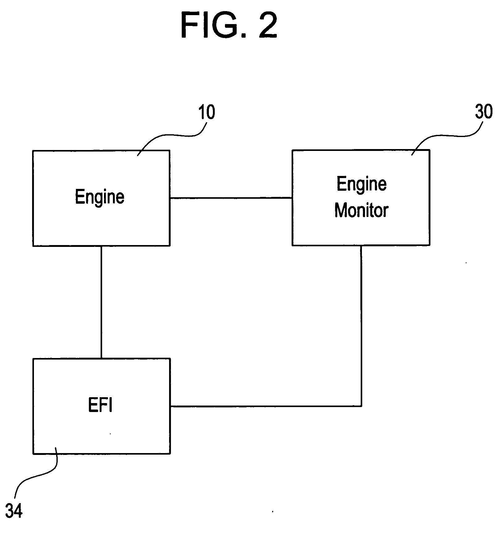
[0020]FIG. 2 is a schematic of one embodiment of the disclosed apparatus for suppressing internal combustion engine emissions. Many of the embodiments are discussed here below with respect to large, medium speed compression ignition engines of the type used on railroad locomotives subject to transient modes of operation, such as arising from changes in engine throttle notch position, differences between commanded and actual engine speed, and the imposition of loads on the engine over short periods of time. A compression ignition engine 10 is shown operatively coupled to an electronic fuel injection system 34. Communicably coupled to the engine 10 and electronic fuel injection system 34 is an engine monitor 30. In this embodiment, the engine monitor 14 monitors the engine, and determines when the engine is in a transient mode. In another embodiment, the electronic fuel injection system 34 may incorporate the engine monitor 30. When in a transient mode, the monitor 30 communicates thi...


PUM


Abstract

A method of reducing emissions from a large, medium speed fuel injected diesel engine of the type used on locomotives subject to transient modes of engine operation in which the engine is accelerated or increased loads are applied. The method comprises: monitor at least one operating parameter of the diesel engine; determining, based on such operating parameter, whether the diesel engine is in a transient mode; and controlling a timing of fuel injection to cylinders of the engine, to retard the timing when the diesel engine is in a transient mode relative to the timing of fuel injection when the diesel engine is not in a transient mode of operation.

Description

BACKGROUND OF THE INVENTION [0001] The invention relates generally to the suppression of emissions generation from internal combustion engines and, more particularly, to a fuel injection control system that suppresses emission generation. [0002] Internal combustion engines, such as compression ignition engines are well known for producing black smoke or heavy particulate emissions during acceleration or load ascending transients. One cause of this phenomenon is incomplete fuel-air mixing during the injection and combustion of the fuel injected in compression cylinders during these acceleration and load ascending transient engine operating modes. [0003] A basic combustion process for compression ignitions involves a diffusion type combustion of liquid fuel. As liquid fuel is injected into compressed hot cylinder air, it evaporates and mixes with the surrounding air to form a flammable mixture. This is a continuing process that happens over time as the fuel is injected into the cylind...

Claims


Application Information

Patent Timeline
Patent Type & Authority Applications(United States)
IPC IPC(8): F02D41/04F02D41/08F02D41/10F02D41/40
CPCF02D41/045F02D41/083Y02T10/44F02D41/401F02D2250/38F02D41/10Y02T10/40
Inventor GLENN, DOUGLASKOTHAPALLI, VENKATARAMESH VARMAMISCHLER, JAMES ROBERT
Owner GE GLOBAL SOURCING LLC
Why Eureka
Try Eureka