Combined material layering technologies for electric heaters

Active Publication Date: 2005-07-07
WATLOW ELECTRIC MFG
View PDF17 Cites 99 Cited by
  • Summary
  • Abstract
  • Description
  • Claims
  • Application Information

AI Technical Summary

Benefits of technology

[0006] In one preferred form, the present invention provides a layered heater comprising a dielectric layer formed by a first layered process, a resistive layer formed on the dielectric layer, the resistive layer formed by a second layered process, and a protective layer formed on the resistive layer, wherein the protective layer is formed by one of the first or s

Problems solved by technology

With thick film layered heaters, the type of material that may be used as the substrate is limited due to the incompatibility of the thick film layered processes with certain substrate materials.
For example, 304 stainless steel for high temperature applications is without a compatible thick film dielectric material due to the relatively high coefficient of thermal expansion of the stainless steel substrate.
The thick film dielectric materials that will adhere to this stainless steel are most typically limited in temperature that the system can endure before (a) the dielectric becomes unacceptably “conductive” or (b)

Method used


Image

  • Combined material layering technologies for electric heaters
  • Combined material layering technologies for electric heaters
  • Combined material layering technologies for electric heaters

Examples


Embodiment Construction

[0027] The following description of the preferred embodiments is merely exemplary in nature and is in no way intended to limit the invention, its application, or uses.

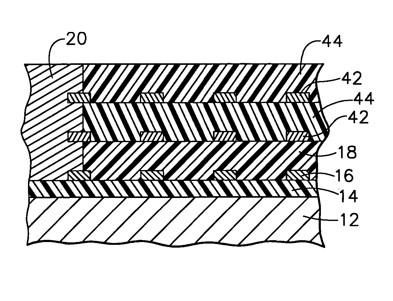
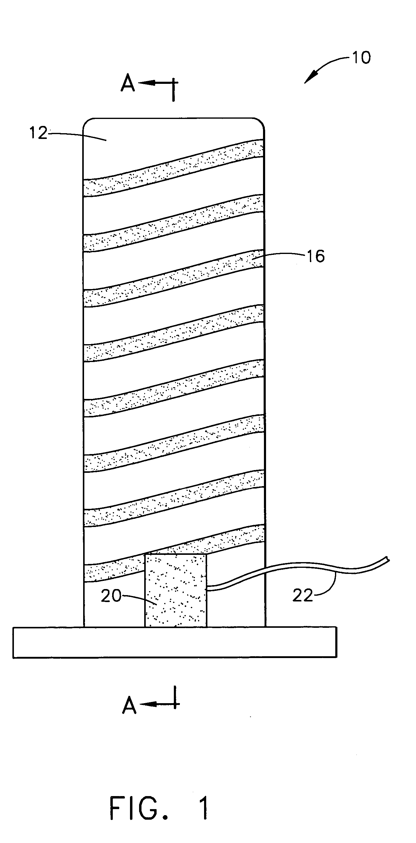
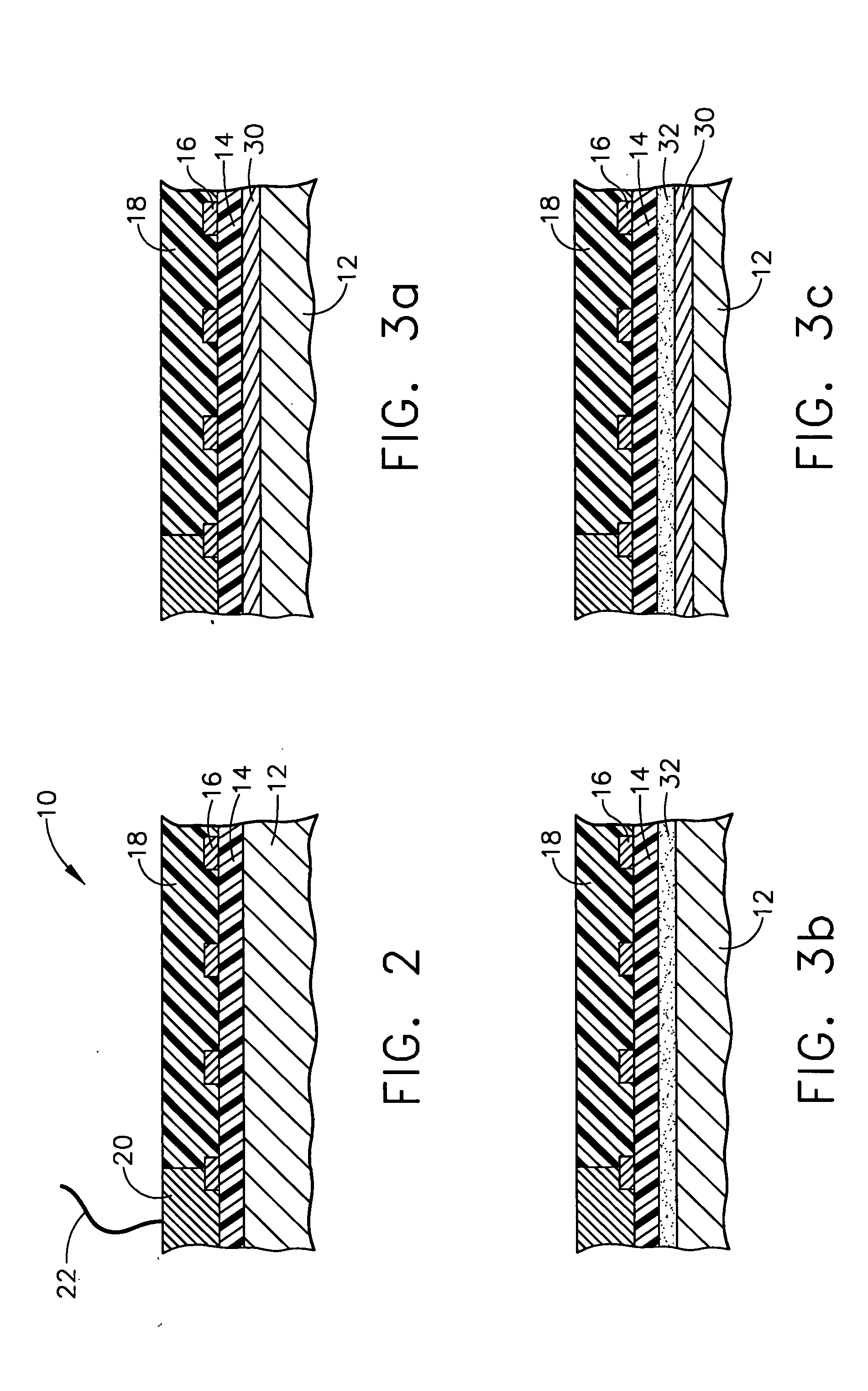
[0028] Referring to FIGS. 1 and 2, a layered heater in accordance with one form of the present invention is illustrated and generally indicated by reference numeral 10. The layered heater 10 comprises a number of layers disposed on a substrate 12, wherein the substrate 12 may be a separate element disposed proximate the part or device to be heated, or the substrate 12 may be the part or device itself. As best shown in FIG. 2, the layers preferably comprise a dielectric layer 14, a resistive layer 16, and a protective layer 18. The dielectric layer 14 provides electrical isolation between the substrate 12 and the resistive layer 16 and is formed on the substrate 12 in a thickness commensurate with the power output, applied voltage, intended application temperature, or combinations thereof, of the layered heater 10. The...


PUM


Abstract

A layered heater is provided that comprises a dielectric layer formed by a first layered process, a resistive layer formed on the dielectric layer, the resistive layer formed by a second layered process, and a protective layer formed on the resistive layer, wherein the protective layer is formed by one of the first or second layered processes or yet another layered process. The first layered process is different than the second layered process in order to take advantage of the unique processing benefits of each of the first and second layered processes for a synergistic result. The layered processes include, by way of example, thick film, thin film, thermal spraying, and sol-gel. Additional functional layers are also provided by the present invention, along with methods of forming each of the individual layers.

Description

FIELD OF THE INVENTION [0001] The present invention relates generally to electrical heaters and more particularly to methods of forming individual layers of a layered electrical heater. BACKGROUND OF THE INVENTION [0002] Layered heaters are typically used in applications where space is limited, when heat output needs vary across a surface, where rapid thermal response is desirous, or in ultra-clean applications where moisture or other contaminants can migrate into conventional heaters. A layered heater generally comprises layers of different materials, namely, a dielectric and a resistive material, which are applied to a substrate. The dielectric material is applied first to the substrate and provides electrical isolation between the substrate and the electrically-live resistive material and also minimizes current leakage to ground during operation. The resistive material is applied to the dielectric material in a predetermined pattern and provides a resistive heater circuit. The la...

Claims


Application Information

Patent Timeline
IPC IPC(8): H05B3/28
CPCH05B3/28
Inventor MCMILLIN, JAMESSTEINHAUSER, LOUIS P.PTASIENSKI, KEVIN
Owner WATLOW ELECTRIC MFG
Why Eureka
Try Eureka