
Photocatalytic nanocomposites and applications thereof

a nanocomposite and photocatalyst technology, applied in the direction of catalyst activation/preparation, organic compound/hydride/coordination complex catalyst, physical/chemical process catalyst, etc., can solve the problems of loss of membrane structure and membrane function, lack of conventional method efficiency, and certain bacteria that can be harmful or even deadly to humans and animals. , to achieve the effect of effective destruction of biological agents

Inactive Publication Date: 2008-02-21
UNIV OF FLORIDA RES FOUNDATION INC
View PDF5 Cites 91 Cited by
  • Summary
  • Abstract
  • Description
  • Claims
  • Application Information

AI Technical Summary

Benefits of technology

[0013] The invention also includes a method of destroying biological agents by irradiating the photocatalyst nanocomposite with light having photon energies which equal or exceed the bandgap energy of the photocatalyst nanocomposite and exposing a fluid contaminated with a biological agent to photocatalyst nanocomposites according to the invention. Since the photocatalyst nanocomposite has been discovered to be imparted significant photocatalytic activity using light in the visible spectrum, irradiation in either the visible range or the ultraviolet range or a broad spectrum provides effective destruction of biological agents. Furthermore, the photocatalyst nanocomposite maintains its activity in the dark for long periods of time after irradiation for short periods of time. This feature permits the method to be practiced using intermittent irradiation, so that periods of darkness are interspersed with periods of irradiation. The cycle of dark and irradiation does not have to be periodic.

Problems solved by technology

Certain bacteria can be harmful or even deadly to humans as well as animals.
Currently, there is a lack of efficiency with the conventional method and further developments are necessary to achieve higher biocidal efficiency.
The loss of membrane structure and membrane functions due to the photochemical oxidation was the root cause of cell death when photocatalytic TiO2 particles are outside the cell.

Method used


Image

  • Photocatalytic nanocomposites and applications thereof
  • Photocatalytic nanocomposites and applications thereof
  • Photocatalytic nanocomposites and applications thereof

Examples


example 1

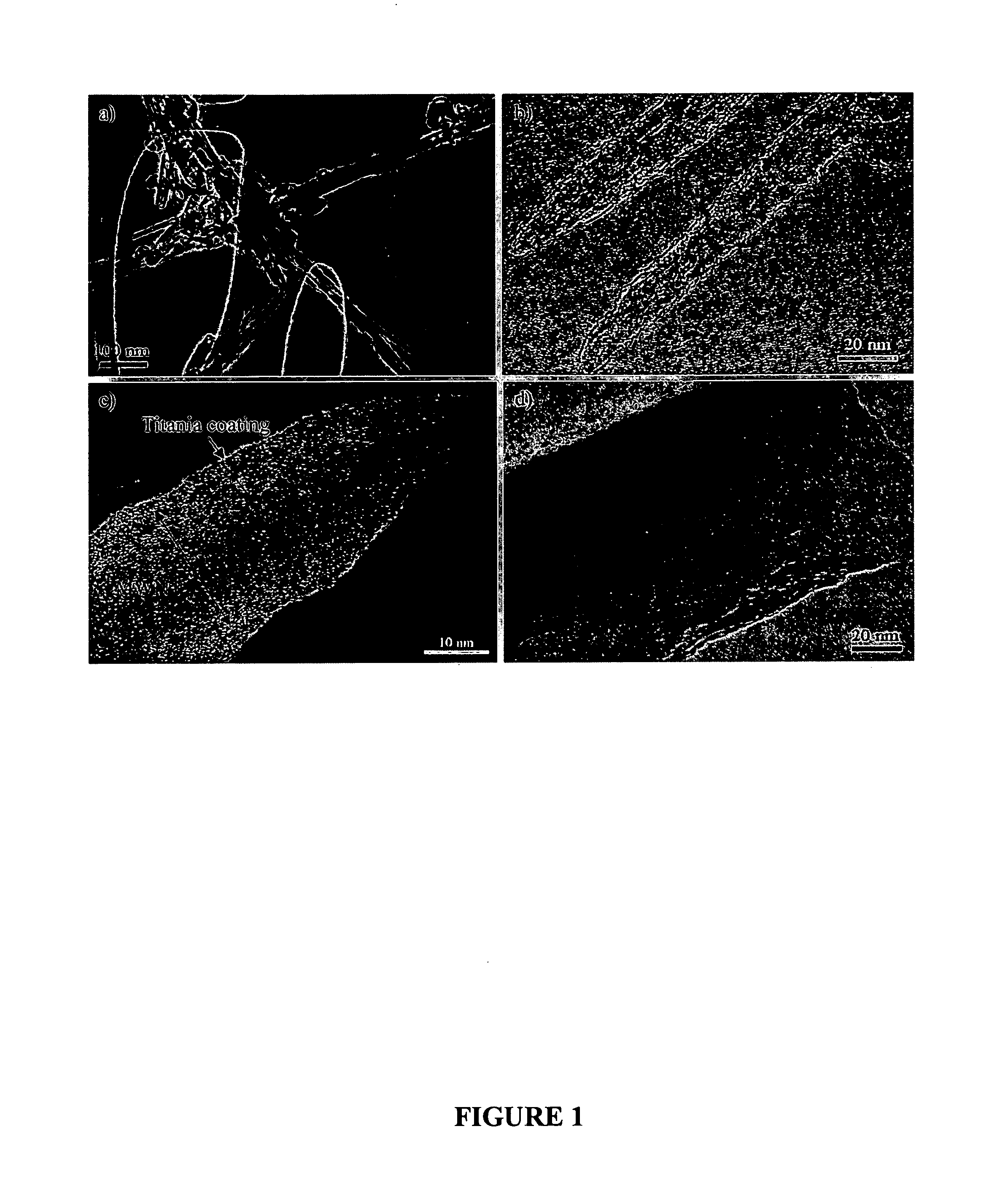
[0037] Synthesis and Characterization of TiO2-MWNT Nanocomposites: Commercially available arc-discharged MWNTs (Alfa Aesar, 3-24 nm outer diameter, 0.5-5 μm) were used as templates and the functionalization of the carbon surfaces was performed by chemical oxidation according to a method disclosed by Tsang et al., Nature, vol. 372, pp. 159-162, 1994. Oxidation was performed by dispersing 300 mg of MWNTs in 200 mL of 70% HNO3 by sonification for 30 minutes followed by refluxed with magnetic stirring at 140° C. for 10 hours. In this manner the MWNT surface was modified so that a thin layers of metal oxides could be attached via sol-gel processing. Although not used in this Example, uniformity of the suspension of the nanotubes in the solution can be aided by stabilizing agents, such as surfactants (e.g. sodium dodecyl sulfate (SDS)) and certain polymers.

[0038] The nanotubes obtained had an outer diameter less than 20 nm and their surfaces were partially covered with acidic functional ...

example 2

[0042] Spore Preparation and Biocidal Test: B. cereus ATTC 2 was used as a surrogate of Bacillus anthracis. The bacteria were inoculated in 500 mL Erlenmeyer flasks containing 99 mL of Columbia broth supplemented with 1 mL of 10 mM MnSO4.H2O. Foam plugs were used to allow air access and prevent contamination. Liquid cultures were incubated for three days at 35±2° C. an orbital incubator-shaker (Model C24, New Brunswick Scientific) at 250 rev / min. Spores were harvested and purified using the lysozyme treatment. The heat shock treatment (80° C., 10 minutes) was applied following the purification process to ensure killing of vegetative cells. Spore suspensions were stored in sterile deionized water and refrigerated at 4° C. until use. Three types of spore suspensions were prepared; (i) the control sample by suspending 10 mL of spore suspension in 20 mL of sterile deionized water, (ii) the experimental sample with 3 mg of commercial TiO2 nanoparticles (Degussa P25, primarily anatase wit...

example 3

[0052] Photocatalytic activity of TiO2-MWNT in visible light: The photocatalytic activity of TiO2-MWNT was displayed by the degradation of a dye in aqueous solution. A 3 mg sample of TiO2-MWNT was dispersed in 50 mL of a 5 ppm PROCION RED MX-5B™ (naphthalenedisulfonic acid, 5-((4,6-dichloro-s-triazin-2-yl)amino)-4-hydroxy-3-(phenylazo)-, disodium salt) solution by sonification for 20 minutes. The suspension was then placed under halogen lamps of a total power of 50 W / m2 which had no output of UV light. Every 20 minutes a sample was removed and the dye concentration was measured by UV-VIS spectroscopy. As can be seen in FIG. 6, the concentration of dye reduced to approximately half its initial concentration in 100 minutes. Under similar conditions with the Degussa P25 TiO2 control, no measurable degradation of the dye occurred over the two hour period.


PUM

PropertyMeasurementUnit
Temperatureaaaaaaaaaa
Thicknessaaaaaaaaaa

Abstract

A photocatalyst nanocomposite which can be used to destroying biological agents includes a carbon nanotube core, and a photocatalyst coating layer covalently or ionically bound to a surface of the nanotube core. The coating layer has a nanoscale thickness. A method of forming photocatalytic nanocomposites includes the steps of providing a plurality of dispersed carbon nanotubes, chemically oxidizing the nanotubes under conditions to produce surface functionalized nanotubes to provide C and O including groups thereon which form ionic or covalent bonds to metal oxides, and processing a metal oxide photocatalyst sol-gel precursor in the presence of the nanotubes, wherein a nanoscale metal oxide photocatalyst layer becomes covalently or ionically bound to the nanotubes.

Description

CROSS-REFERENCE TO RELATED APPLICATIONS [0001] The present application claims the priority of U.S. provisional patent application No. 60 / 605,854 filed on Aug. 31, 2004 and entitled “Photocatalytic Nanocomposites and Applications Thereof”.STATEMENT REGARDING FEDERALLY SPONSORED RESEARCH OR DEVELOPMENT [0002] The U.S. Government has certain rights to the invention based on National Science Foundation Grant No. EEC-94-02989.FIELD OF THE INVENTION [0003] This invention relates to photocatalyst coated nanotubes and applications thereof including use as a biocide. BACKGROUND OF THE INVENTION [0004] Certain bacteria can be harmful or even deadly to humans as well as animals. In September 2001, anthrax spores were mailed to several locations via the US Postal Service resulting in twenty-two confirmed or suspected cases of anthrax infection. Because the possibility of a terrorist attack using bioweapons is especially difficult to predict, detect, or prevent in a conventional way, it is cruci...

Claims


Application Information

Patent Timeline
IPC IPC(8): A62D3/17B01J31/00
CPCA61L9/205B01J21/063B01J21/185B01J35/004C02F2305/10B82Y30/00C02F1/32C02F1/725B01J37/0217B01J35/39
Inventor SIGMUND, WOLFGANG M.LEE, SUNG-HWANKOOPMAN, BENJAMINMOUDGIL, BRIJPYRGIOTAKIS, GEORGIOSKRISHNA, VIJAY
Owner UNIV OF FLORIDA RES FOUNDATION INC
Learn More