Driver for an ultrasonic transducer and an ultrasonic transducer

Active Publication Date: 2005-07-07
THE HONG KONG POLYTECHNIC UNIV
View PDF9 Cites 20 Cited by
  • Summary
  • Abstract
  • Description
  • Claims
  • Application Information

AI Technical Summary

Benefits of technology

[0008] It is an object of the present invention to provide a driver for an ultrasonic transducer, and an ultrasonic transducer, for wire bonding applications that has

Problems solved by technology

A problem with piezoelectric ultrasonic transducers is that they are subject to accelerated aging and fail when operating at elevated electrical, mechanical and/or temperature stress to increase mechanical power output.
These transducers are not considered inherently reliable in high-power applications.
Although multiple piezoelectric elements could be combined or grouped to produce transducers with increased power-handling capability this would result in inefficient

Method used


Image

  • Driver for an ultrasonic transducer and an ultrasonic transducer
  • Driver for an ultrasonic transducer and an ultrasonic transducer
  • Driver for an ultrasonic transducer and an ultrasonic transducer

Examples


second embodiment

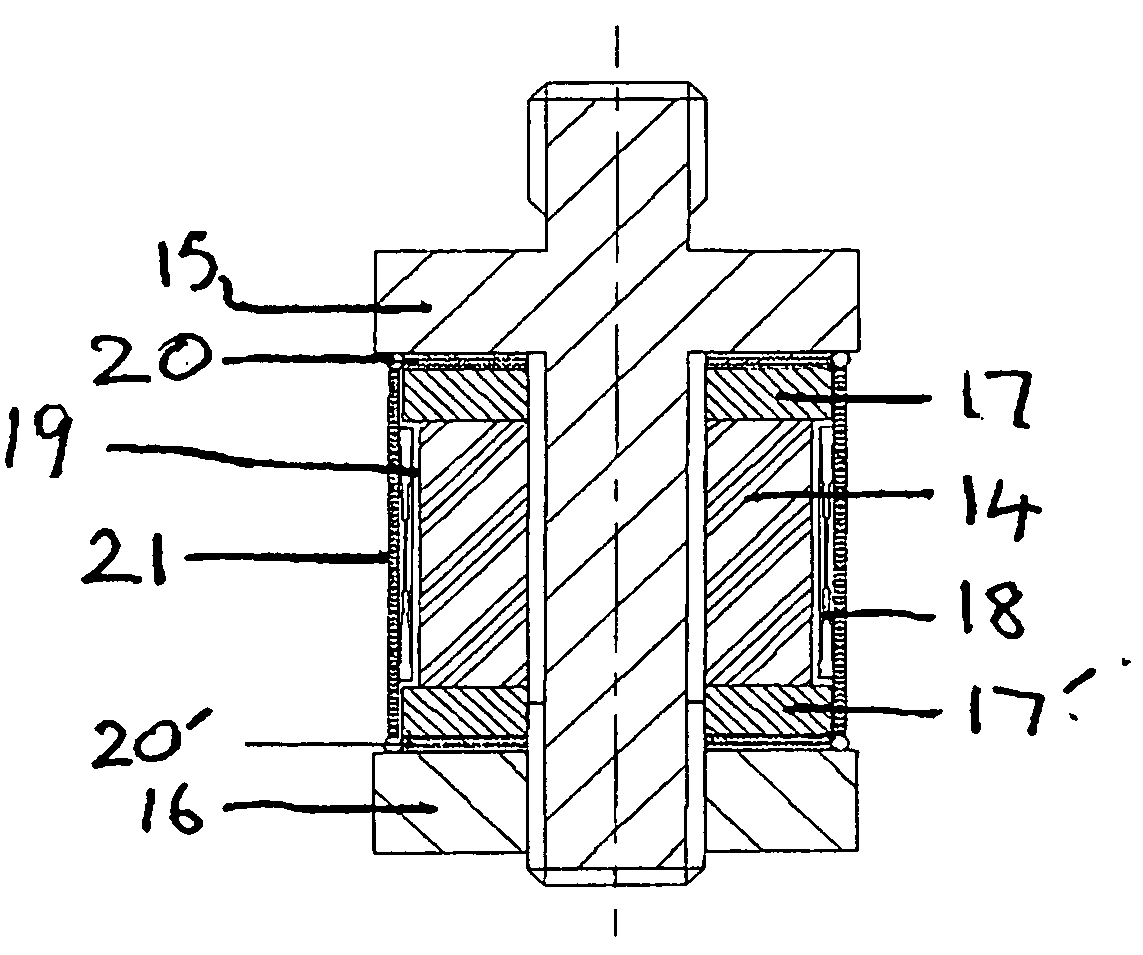
[0045] Referring to FIG. 5, in second embodiment of the driver the threaded shaft 15 and a monolithic magnetic return-path ring 20 are manufactured into a single component, while the nut 16 is combined with another monolithic magnetic return-path ring 20′ to form another single component.

third embodiment

[0046] Referring to FIG. 6, in the driver the threaded shaft 15, a monolithic magnetic return-path ring 20 and a monolithic permanent magnet ring 17 are manufactured into a single component, while the nut 16 is combined with another monolithic magnetic return-path ring 20′ and another monolithic permanent magnet ring 17′ to form another single component.

[0047] A layer of thick-film or thin-film magnetic return-path and / or a layer of thick-film or thin-film permanent magnet can be coated on the contacting surface of both the threaded shaft 15 and nut 16 by using thick-film technology and thin-firm techniques (i.e., sputtering, pulsed laser deposition (PLD), etc.), respectively. This design is advantageous in minimizing the number of components and hence the number of component interfaces appeared in the driver 5, thereby increasing the flexibility of assembly as well as the quality and reliability of the resulting driver 5. In general, giant magnetostrictive ultrasonic drivers / transd...


PUM

PropertyMeasurementUnit
Pressureaaaaaaaaaa
Magnetic fieldaaaaaaaaaa
Permeabilityaaaaaaaaaa

Abstract

An ultrasonic transducer driver has a giant magnetostrictive element, a fastener for holding the giant magnetostrictive element under mechanical pressure, a first field generator for providing a magnetic bias field, a second field generator for providing a magnetic drive field and a magnetic circuit for channelling the magnetic fields in the magnetostrictive element. An ultrasonic transducer for a bonding apparatus has a horn having a bonding tool at its smaller end and a mounting barrel adjoined onto it. The driver coupled to the larger end of the horn.

Description

BACKGROUND OF THE INVENTION [0001] 1. Field of the Invention [0002] The invention relates to drivers for ultrasonic transducers and to ultrasonic transducers. In particular the invention relates to a driver and ultrasonic transducer for use as a bonding apparatus in wire-bonding machines. [0003] 2. Description of Prior Art [0004] Ultrasonic transducers on wire-bonding machines are used to apply pressure-and ultrasonic energy simultaneously for connecting the lead wires from a semiconductor component to a substrate. The ultrasonic transducer has an ultrasonic driver for converting driving signals from an ultrasonic signal generator into ultrasonic vibrations. A horn amplifies the ultrasonic vibrations from the driver and a bonding tool, which is normally in the form of a wedge or a capillary, located at the smaller end of the horn couples the amplified ultrasonic vibrations while applying a predetermined bond force to the lead wires and components being bonded together. Piezoelectric...

Claims


Application Information

Patent Timeline
IPC IPC(8): B06B1/08B23K20/10H01L41/12H04R15/00
CPCB06B1/08H01L41/12B23K20/106H01L2224/78301H10N35/00
Inventor OR, SIU WINGYUNG, CHUNG SHEUNGCHAN-WONG, HELEN LAI WA
Owner THE HONG KONG POLYTECHNIC UNIV
Why Eureka
Try Eureka