Active cooling system for cpu

a cooling system and active technology, applied in the direction of electrical apparatus casings/cabinets/drawers, semiconductor/solid-state device details, instruments, etc., can solve the problems of processor overheating, insufficient cooling of computer processors, and increasing switching speeds

Inactive Publication Date: 2005-07-07
ACTIVE COOL RES & DEV LTD
View PDF9 Cites 43 Cited by
  • Summary
  • Abstract
  • Description
  • Claims
  • Application Information

AI Technical Summary

Benefits of technology

[0018] Preferably, the microprocessor is programmed to detect rapid temperature changes of processor via said temperature sensor, allowing the microprocessor to predict heavy processor loads and to trigger maximum cooling.

Problems solved by technology

As the state of the art computer processors become ever more powerful, their switching speeds are increasing, and there is a significant problem of processor overheating.
Existing solutions for cooling computer processors are proving inadequate to meet the heat dissipation requirements upon them, and this problem is becoming more serious as time passes.
Since increasing the operating temperature of a CPU critically affects its reliability, and thus the reliability of the entire computer system it is a part of, the currently available cooling technologies are stretched to their limit.
The Marlow device is powered by the power supply of the computer, hence has limited capabilities.
Since it cannot receive sufficient power to dissipate the heat generated by current processors, its heat dissipation capacity is too low to meet the requirements of present day CPUs.
Because of its inherent disadvantages, particularly it not being able to meet the cooling demands of later generations of CPUs power requirements, the Marlow device ceased to be marketed by the beginning of the year 2000.
Overcooling may result in water vapour condensing on the unit's cold side, and this can lead to serious problems, particularly in some climates having high ambient temperatures and humidity levels.
Current solutions, based on passive heat sinks and fans, are only just able to cope with currently available processors, enabling them to function reliably and stably.
They will be unable to handle the expected heat dissipation demands of the next generation of processors.
Even when the average temperature of the processor is kept within acceptable limits, “hot spots” (local areas of high temperature within the processor), can cause instability, processor failure and damage.
In consequence, hot spots may cause serious problems.
It is anticipated that as successive generations of processors will generate more heat, the problem of hot spots will become increasingly critical.

Method used


Image

  • Active cooling system for cpu
  • Active cooling system for cpu
  • Active cooling system for cpu

Examples


second embodiment

[0048] With reference now to FIGS. 3a and 3b, there is shown the parts of the present invention: a Cool Card 220 having the form factor of being mounted on the TEC / HEAT sink assembly 200. Power cord 201 is connected to the electrical mains, providing power to the computer power supply 203. One of the standard output connectors 208 of the computer power supply 203 is connected to the Cool Card 220 mounted on the side of the TEC 217 / heat sink 215 assembly. The cool card 220 is mounted onto the heat sink 215, but separated therefrom by spacers 223, and is fastened in place with appropriate fastening means, such as screws 222 for example. A blue indicator LED 207 is mounted onto the cool card 220. The controlled-power output of the Cool Card is supplied at output connector 209 via wires 212 to the TEC element 218. The temperature sensor 224 is connected via wire 213 to connector 209. The cold side of the TEC element 218 is attached to the cold plate 217, which is typically aluminum, cop...

third embodiment

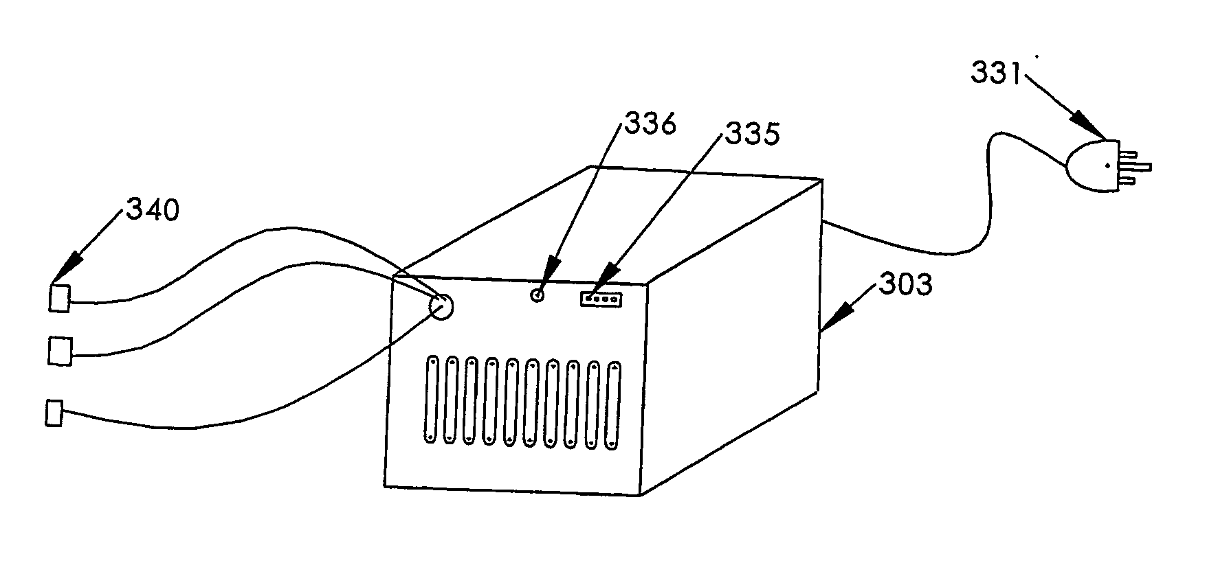
[0049]FIGS. 4a and 4b show the present invention, wherein the Cool Card has the form factor of being mounted inside a modified computer power supply.

[0050] Here, power cord 331 is connected to the electrical mains, providing power to the computer power supply 303, and the Cool Card 340 is mounted inside the power supply 303, and receives 12 V DC and 5 V DC from the power supply board via wire 337. Preferably, a blue indicator LED 336 is mounted on the outside of the power supply 303 and is connected to the Cool Card 340 via wire 343. The controlled-power output of the Cool Card is supplied at output connector 309 via wires 338 to connector 335, located on the side of the power supply facing the interior of the computer.

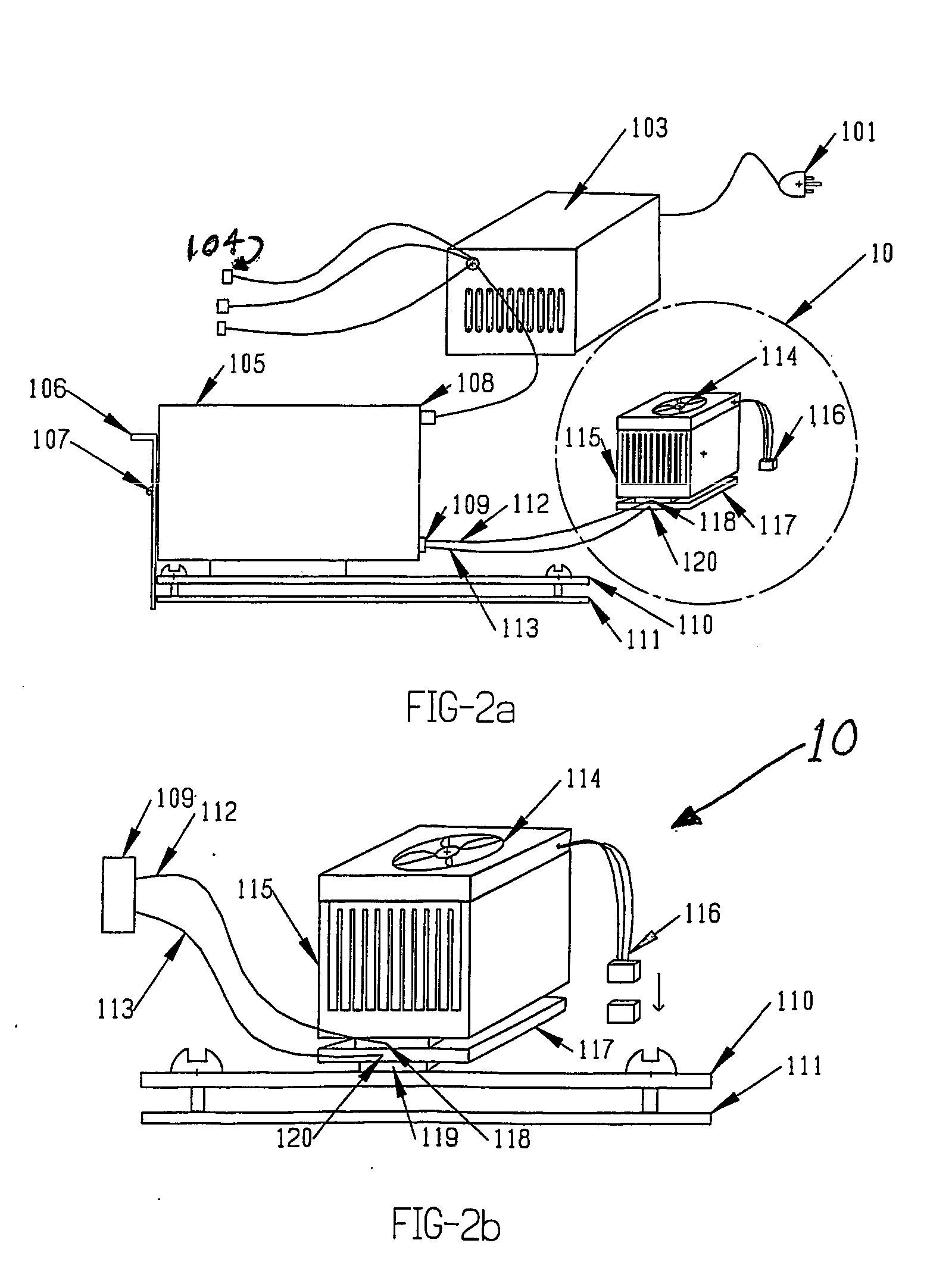
[0051] The connector 335 may be coupled via connector 109 (FIG. 2), supplying power for the TEC 118 (FIG. 2) and further coupled via wire 113 (FIG. 2) to temperature sensor 120 (FIG. 2) located on cold plate 117 (FIG. 2). The cold side of the TEC element 118, (FIG. 2...


PUM


Abstract

A cooling system for cooling a processor installed within a computer case, the active cooling system comprising: (i) a TEC/heat-sink assembly comprising a thermoelectric cooling module (TEC) having a cold plate and a hot plate, the cold plate being coupleable to a processor, for removing heat from the processor, and the hot plate being coupled to a heat sink ; (ii) a control microprocessor controllingly coupled to a power inverter, said power inverter for provision of high efficiency cooling to the processor by application of an appropriate voltage to the TEC; the control microprocessor being further coupled to (iii) a temperature sensor located on the cold plate of the TEC, for providing information to the microprocessor regarding temperature of the TEC; said cooling system being powered by a standard PC power supply having sufficient power to accommodate power demands of both the PC and the cooling system.

Description

FIELD OF THE INVENTION [0001] The present invention relates to a device and method for actively cooling a computer microprocessor (CPU), preventing over-heating and facilitating higher switching speeds. BACKGROUND OF THE INVENTION [0002] As the state of the art computer processors become ever more powerful, their switching speeds are increasing, and there is a significant problem of processor overheating. [0003] Existing solutions for cooling computer processors are proving inadequate to meet the heat dissipation requirements upon them, and this problem is becoming more serious as time passes. [0004] The heat generated by a working CPU is a function of the density of transistors (CMOS devices) in the chip and of switching speed. Each CPU model had several versions of switching speed, and the switching speed and temperature were correlated. [0005] The processors of early personal computers such as Intel's XT, 286 and 386 chips don't need heat dissipation. Their power consumption is l...

Claims


Application Information

Patent Timeline
Patent Type & Authority Applications(United States)
IPC IPC(8): G06F1/20H01L23/34H01L23/38H05K7/20
CPCG06F1/20H01L23/34H01L23/38H05K7/20209H01L2924/0002H01L2924/00
Inventor MEIR, RONEN
Owner ACTIVE COOL RES & DEV LTD
Why Eureka
Try Eureka