High frequency signal receiver and semiconductor integrated circuit

a high-frequency signal and integrated circuit technology, applied in the direction of digital transmission, gain control, phase-modulated carrier system, etc., can solve the problems of deterioration of reception characteristics, inability to suppress interference waves by analog filters having cutoff frequencies of 2.4 mhz, etc., to achieve a wide dynamic range and compensate for the deterioration of the pass-band characteristic of the first filter

Inactive Publication Date: 2005-07-07
RENESAS TECH CORP
View PDF8 Cites 58 Cited by
  • Summary
  • Abstract
  • Description
  • Claims
  • Application Information

AI Technical Summary

Benefits of technology

[0023] In the high frequency signal receiver according to the present invention, the controller determines a level of the interference wave in the received signal based on an output signal from the interference wave detection circuit, and controls the first filter to operate in a predetermined bandwidth and the AD converter to operate in a predetermined dynamic range when the level of the interference wave in the receive

Problems solved by technology

However, in the narrow band blocking in the band 2 in the WCDMA, since the frequency of the interference wave approximates the desired signal frequency whose offset frequency is 2.7 MHz, it is impossible to suppress the interference wave by the analog filter having the cutof

Method used


Image

  • High frequency signal receiver and semiconductor integrated circuit
  • High frequency signal receiver and semiconductor integrated circuit
  • High frequency signal receiver and semiconductor integrated circuit

Examples


first embodiment

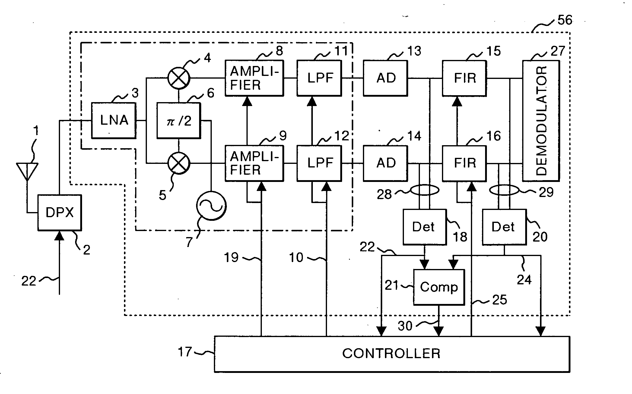
[0040]FIG. 1 shows a high frequency receiver according to the present invention. The high frequency receiver of the present invention comprises a duplexer (DPX) 2 connected to an antenna 1 for separating a transmission signal and received signal, a reception system circuit 56 and a controller (processor) 17. The duplexer 2 is connected to a transmission system circuit so as to receive an output signal 22 from the transmission system. However, since the transmission system circuit has no relation to the present invention, it is omitted from the illustration.

[0041] The reception system circuit 56 has a low noise amplifier (LNA) 3 connected to the duplexer 2, mixers 4 and 5 connected to the LNA 3, a 90-degree phase shifter 6, variable gain amplifiers 8 and 9 for Inphase and Quadraphase connected to the mixers 4 and 5, respectively, analog filters (LPF) 11 and 12 for Inphase and Quadraphase connected to the variable gain amplifiers 8 and 9, respectively, AD converters (ADC) 13 and 14 fo...

second embodiment

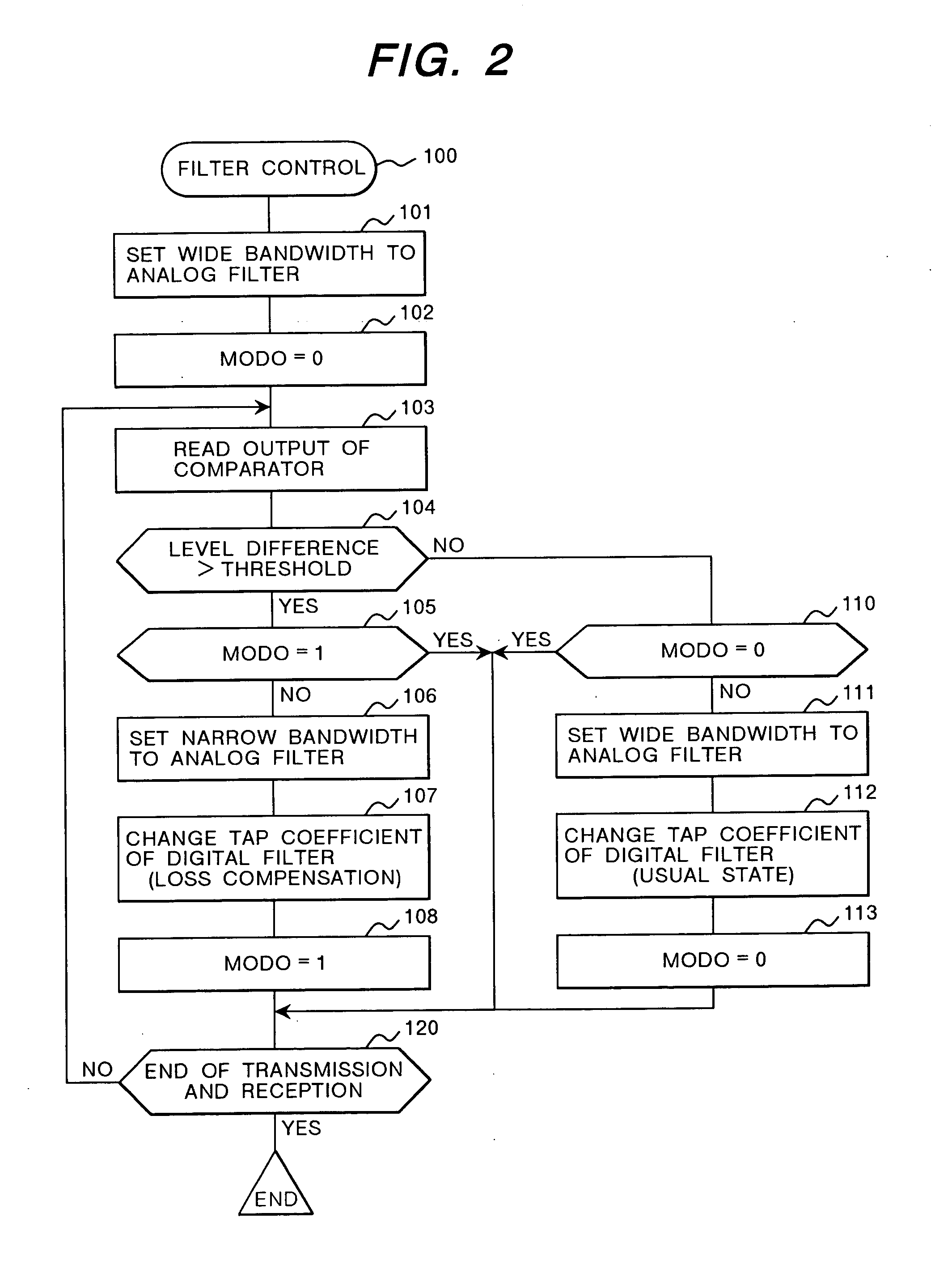
[0061]FIG. 4 shows a flowchart of a gain control routine 200 to be executed by the controller 17 in the

[0062] At the time the transmission / reception system begins operations, the controller 17 performs gain controlling in such a manner that the second level detection signal 24 output from the second detector 20 reaches a predetermined level (Step 201), and reads out the value of the output signal 30 from the comparator 21 (Step 202). In the case where the output signal 30 indicates that the difference between the first level detection signal 22 and the second level detection signal 24 is greater than a predetermined threshold value (Step 203), the controller 17 determines that an interference wave is received. Then, the controller 17 changes the control target, and performs the gain controlling in such a manner that the first level detection signal 22 output from the first detector 18 keeps a predetermined level (Step 204). After that, the controller 17 checks whether the transmissi...

fifth embodiment

[0075]FIG. 7 shows a receiver according to the present invention.


PUM


Abstract

A high frequency signal receiver comprising a variable gain amplifier, a first filter for restricting a bandwidth of an analog baseband signal, an AD converter connected to the first filter, a second filter for restricting the bandwidth of an output of the AD converter, an interference wave detection circuit for detecting the level of an interference wave in the received signal, and a controller for controlling the first filter to have a wide bandwidth when the level of the interference wave is lower than a threshold level, and switching the first filter to have a narrow bandwidth while changing the characteristics of the second filter so as to compensate deterioration of the pass-band of the first filter when the level of the interference wave is equal to or greater than the threshold level.

Description

BACKGROUND OF THE INVENTION [0001] (1) Field of the Invention [0002] The present invention relates to a high frequency signal receiver and a semiconductor integrated circuit, and more particularly to a high frequency signal receiver and a semiconductor integrated circuit, e.g. a mobile terminal, which receives a digitally modulated high-frequency signal and converts the signal into a baseband signal. [0003] (2) Description of Related Art [0004] In Europe, etc., GSM is quite popular as a radio communication system for cellular phone. In Japan, a WCDMA proposed as the third-generation system begins to be used. A communication service using the GSM system has started operations in the 900 MHz band. As the number of subscribers increases thereafter, the frequency band has been extended. Recently, multiband cellular phones that can perform communications in the 1800 MHz band and 1900 MHz band are available. On the other hand, the transmission / reception standard for the WCDMA system (WCDM...

Claims


Application Information

Patent Timeline
IPC IPC(8): H04L27/38H03G3/30H04B1/10H04B1/16H04L27/08H04L27/22
CPCH04B1/1036H03G3/3052
Inventor YAMAMOTO, AKIOIGARASHI, YUTAKAIKUTA, ISAO
Owner RENESAS TECH CORP
Why Eureka
Try Eureka