Autotensioner

Inactive Publication Date: 2005-07-07
BANDO CHEM IND LTD
View PDF10 Cites 24 Cited by
  • Summary
  • Abstract
  • Description
  • Claims
  • Application Information

AI Technical Summary

Benefits of technology

[0038] According to the invention of claim 3, the magnetic force is applied to the magnetorheological fluid in the vibration suppression mechanism in synchronization with the change in the number of the working cylinders. Accordingly,

Problems solved by technology

The oil passes through a small clearance between the piston and the inner surface of the cylinder body to generate high viscous drag, thereby causing a damping effect.
However, in the auxiliary drive system and the valve operating system of the engine configured to idle the cylinders, the belt tension suddenly varies due to a change in output torque of the engine which occurs when the number of working cylinders is changed.
In the valve operating system, in particular, suspending the operation of the intake/exhaust valves of the cylinders may possibly cause direct variation in the belt tension.
However, the damper of the conventional autotensioner does not give a damping resistance which is high enough to prevent the vibration of the moving member of the tensioner caused by the sudden variation in the belt tension.
Therefore, there

Method used


Image

  • Autotensioner
  • Autotensioner
  • Autotensioner

Examples


Example

EMBODIMENT 1

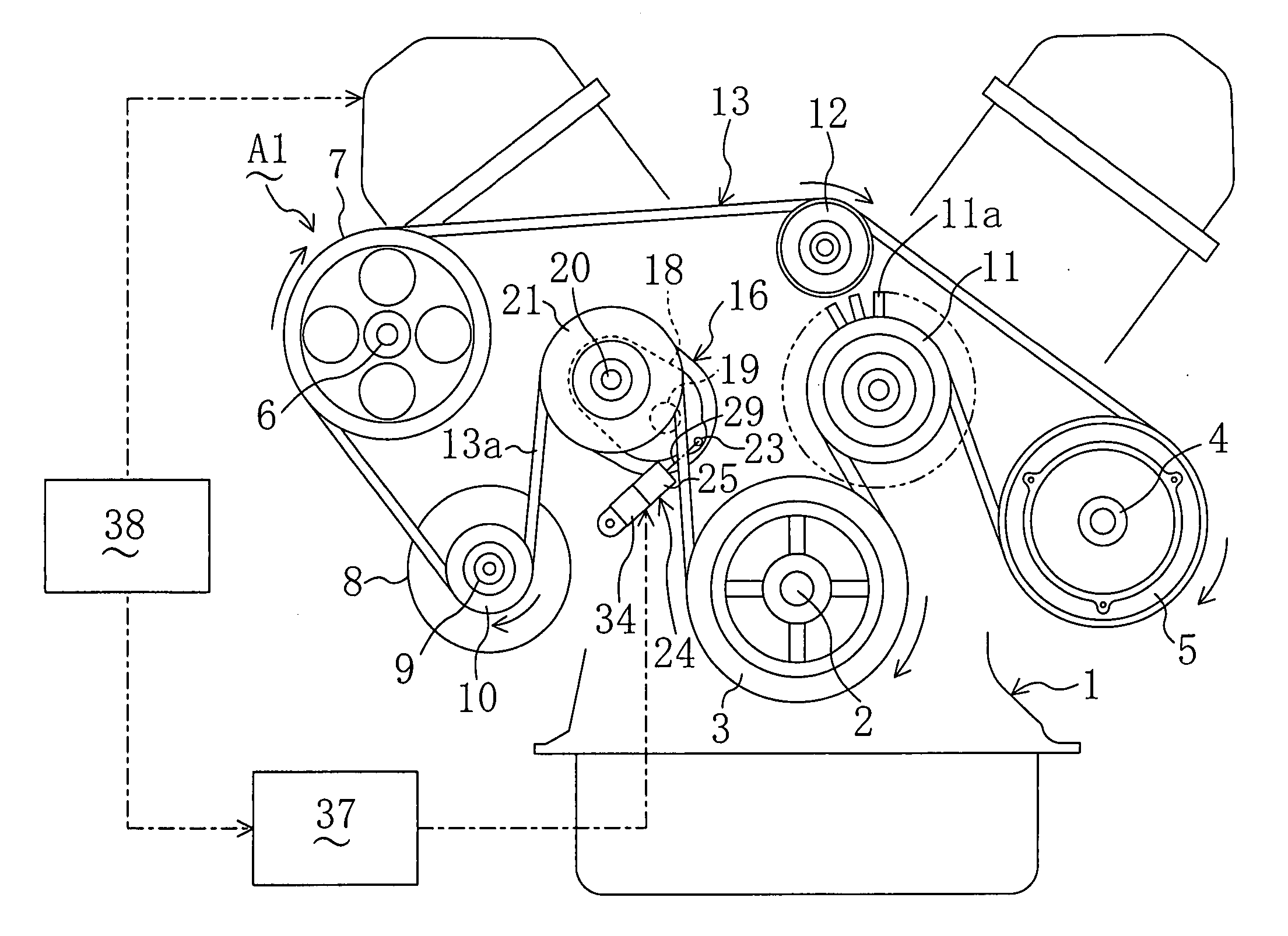
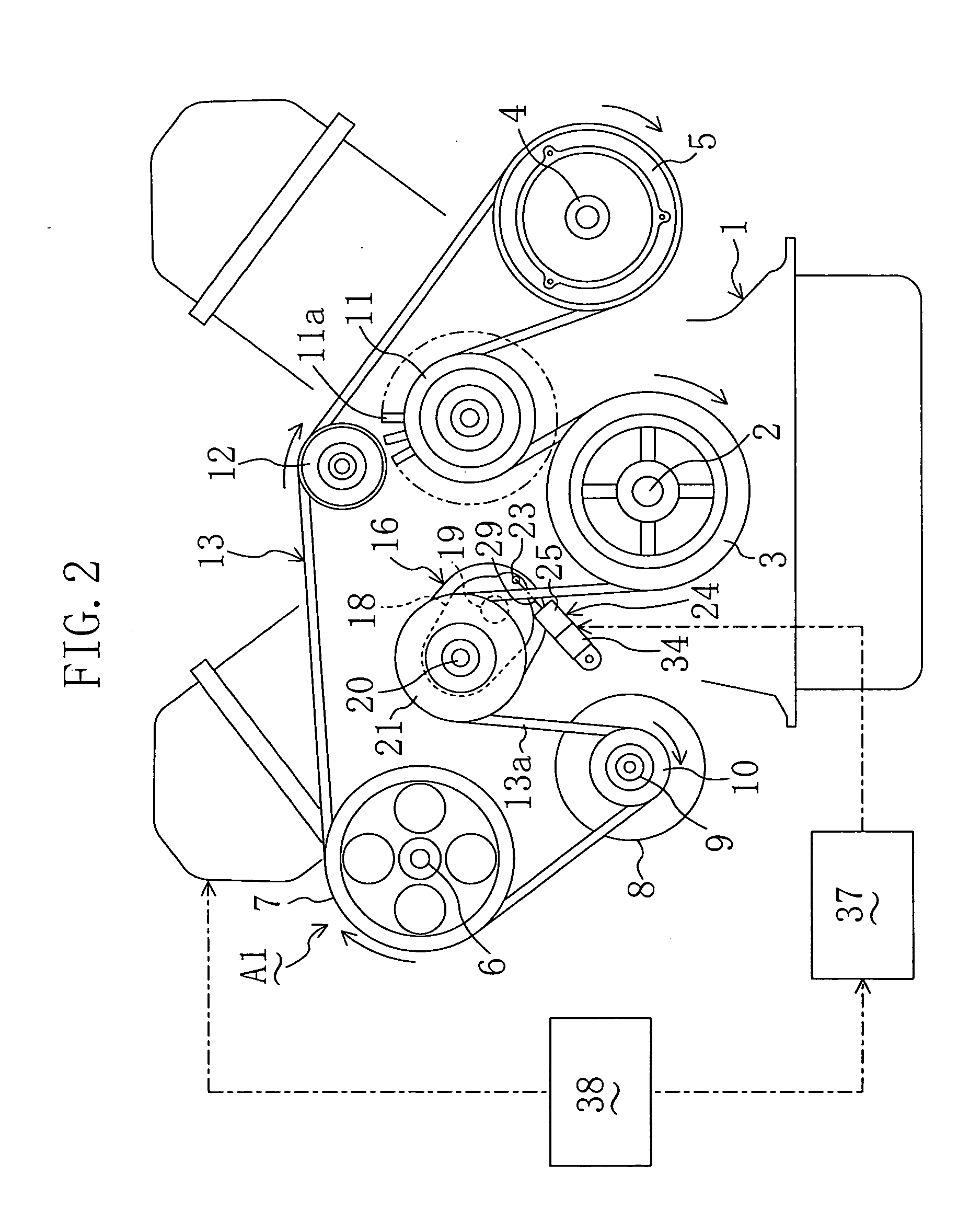
[0048]FIG. 2 illustrates an engine auxiliary drive system A1 as a belt drive system according to Embodiment 1 of the present invention. The auxiliary drive system A1 includes: a V-type multicylinder engine 1 installed in a vehicle; a crank pulley 3 fixed co-rotatably to a crank shaft 2 of the engine 1; a compressor pulley 5 fixed co-rotatably to a rotation shaft 4 of a compressor of an air-conditioning equipment as an auxiliary (not shown); a PS pump pulley 7 fixed co-rotatably to a rotation shaft 6 of a power stealing pump as an auxiliary (not shown); an alternator pulley 10 fixed co-rotatably to a rotation shaft 9 of an alternator 8 as an auxiliary; a fan pulley 11 formed integrally with a cooling fan 11a to drive the cooling fan 11a to rotate; and an idler pulley 12.

[0049] The crank pulley 3, compressor pulley 5, PS pump pulley 7, alternator pulley 10 and idler pulley 12 are V-ribbed pulleys and the fan pulley 11 is a flat pulley. A drive belt 13 which is a V-ribbed...

Example

EMBODIMENT 2

[0075]FIGS. 7 and 8 show Embodiment 2 of the present invention. In the above embodiment, the auxiliary drive system A1 is regarded as the belt drive system and the present invention is applied to the autotensioner 16 including the hydraulic damper 24. In this embodiment, however, a valve operating system for the engine 1 is regarded as the belt drive system and the present invention is applied to an autotensioner 16 including a viscous damper (multiplate viscous damper).

[0076] Though not shown, this embodiment relates to, for example, a valve operating system for driving a cam shaft for driving an intake / exhaust valve in synchronization with the rotation of a crank shaft 2 of the engine 1 with use of a timing belt 45 which is a cogged belt (see FIG. 8). The viscous autotensioner 16 is used for automatic adjustment of the tension of the timing belt 45.

[0077] In FIGS. 7 and 8, reference numeral 46 indicates a fixed hollow cylindrical shaft having a large diameter part 4...


PUM


Abstract

In an autotensioner 16 used in an auxiliary drive system A1 for a multicylinder engine 1 configured to suspend cylinder operation, a damper 24 is provided to suppress the vibration of an arm 18 by means of the viscous drag of a magnetorheological fluid (MRF). The damper 24 is provided with an electromagnet 34 which applies magnetic force to the MRF. When some of the cylinders in the running engine 1 are suspended from working, the electromagnet 34 of the damper 24 is excited in response to a signal from an engine controller 38 to apply the magnetic force to the MRF, thereby increasing the viscous drag of the MRF and suppressing the vibration of the arm 18 or a belt span 13a. In this manner, the vibration of the arm 16 of the tensioner 16 and the belt span 13a is suppressed to prevent the occurrence of an unusual sound and the loss of life of a belt 13.

Description

CROSS-REFERENCE TO RELATED APPLICATION [0001] This non-provisional application claims priority under 35 U.S.C. §119(a) on Patent Application No. 2004-209 filed in Japan on Jan. 5, 2004, the entire contents of which are hereby incorporated by reference. BACKGROUND OF THE INVENTION [0002] (a) Field of the Invention [0003] The present invention relates to an autotensioner which automatically adjusts the tension of a belt in a belt drive system. In particular, it relates to an autotensioner which makes use of the viscous drag of a magnetorheological fluid to suppress the vibration of a moving member associated with a change in the belt tension. [0004] (b) Description of Related Art [0005] Autotensioners of this kind have conventionally been known. Depending on kind of dampers used, they are classified into hydraulic, frictional and viscous autotensioners. Hydraulic and viscous dampers allow damping by using the viscosity of oil and frictional dampers employ the frictional drag of a resi...

Claims


Application Information

Patent Timeline
IPC IPC(8): F01L13/00F16H7/08F16H7/12
CPCF01L1/024F01L13/0005F01L2101/00F16H2007/0885F16H7/0836F16H7/1281F16H2007/0808F16H7/0834F01L2301/00
Inventor MURAO, MASAYUKI
Owner BANDO CHEM IND LTD
Why Eureka
Try Eureka