Spinal implant device

a technology of spinal implants and implants, which is applied in the field of spinal surgery, can solve the problems of laminectomy instability and patients often experiencing difficulty, and achieve the effect of effectively stabilizing one or more spinal vertebrae and being manufactured at low cos

Inactive Publication Date: 2005-07-07
TOZZI JAMES E
View PDF9 Cites 49 Cited by
  • Summary
  • Abstract
  • Description
  • Claims
  • Application Information

AI Technical Summary

Benefits of technology

[0014] It is yet another object of the invention to provide a spinal implant device that is not complex in structure and which can be manufactured at low cost but yet more effectively stabilize one or more spinal vertebrae at the time of laminectomy or for revision posterior spinal surgery.
[0015] In accordance with these and other objects, the present invention is directed to a spinal implant device for stabilizing a vertebrae or for fusing two or more vertebrae, the device being constructed in a number of sizes and shapes to accommodate the particular anatomical structure typical of the cervical, thoracic and lumbar regions of the spine, as well as the different sizes of each depending upon the patient. The device includes a plate-like body having a generall...

Problems solved by technology

Following spinal fusion surgery, patients often experience difficulty due to post lamin...

Method used


Image

  • Spinal implant device
  • Spinal implant device
  • Spinal implant device

Examples


first embodiment

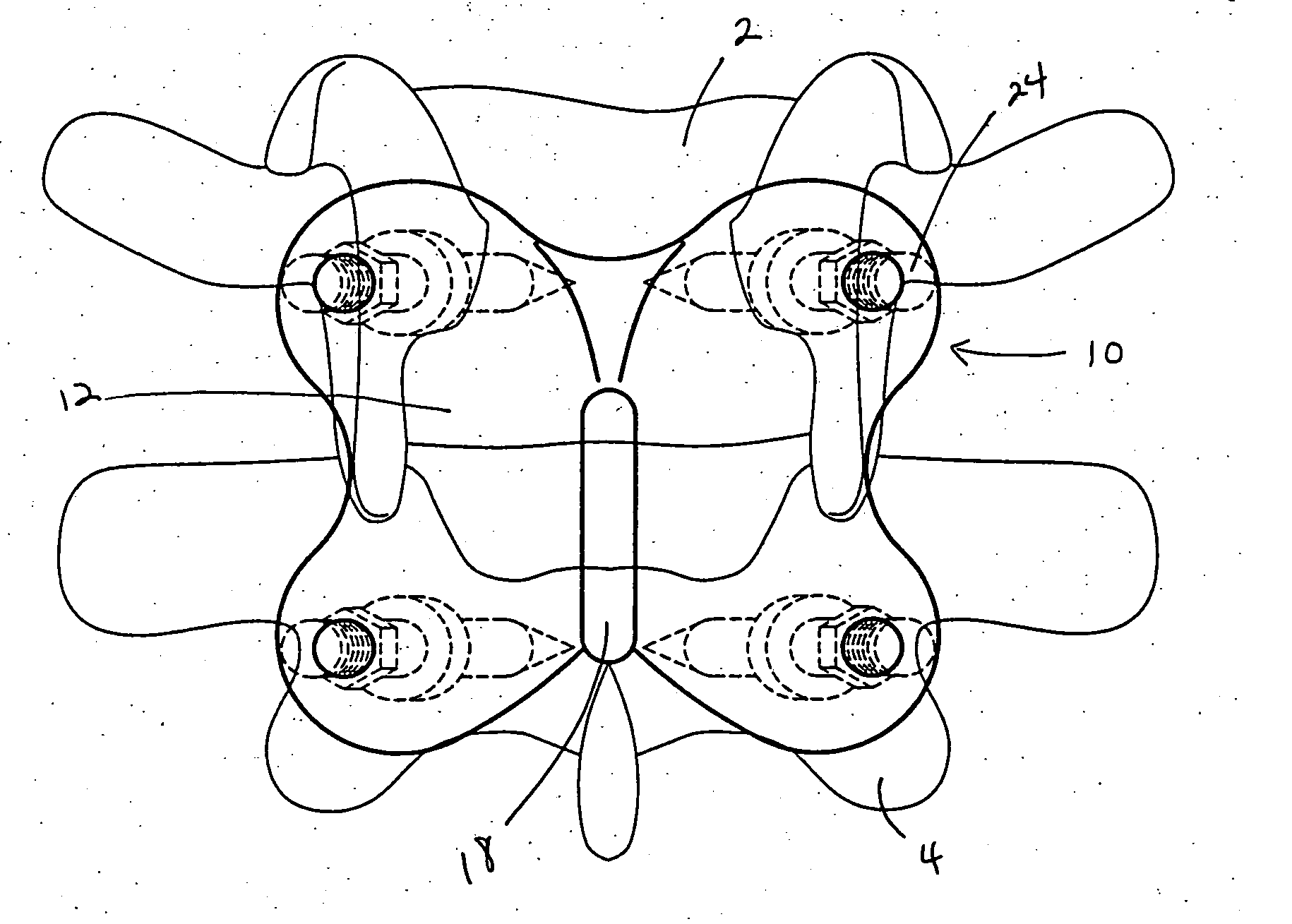
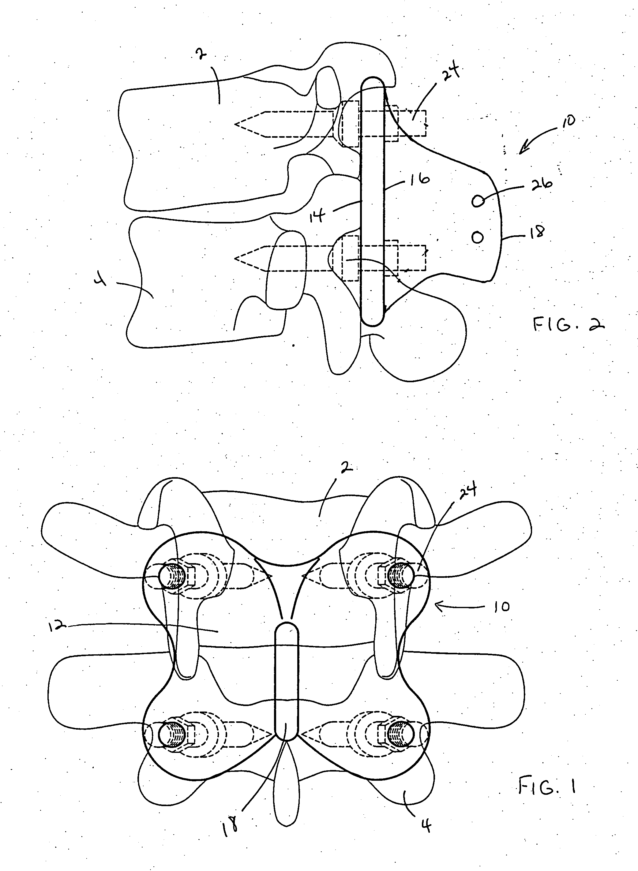
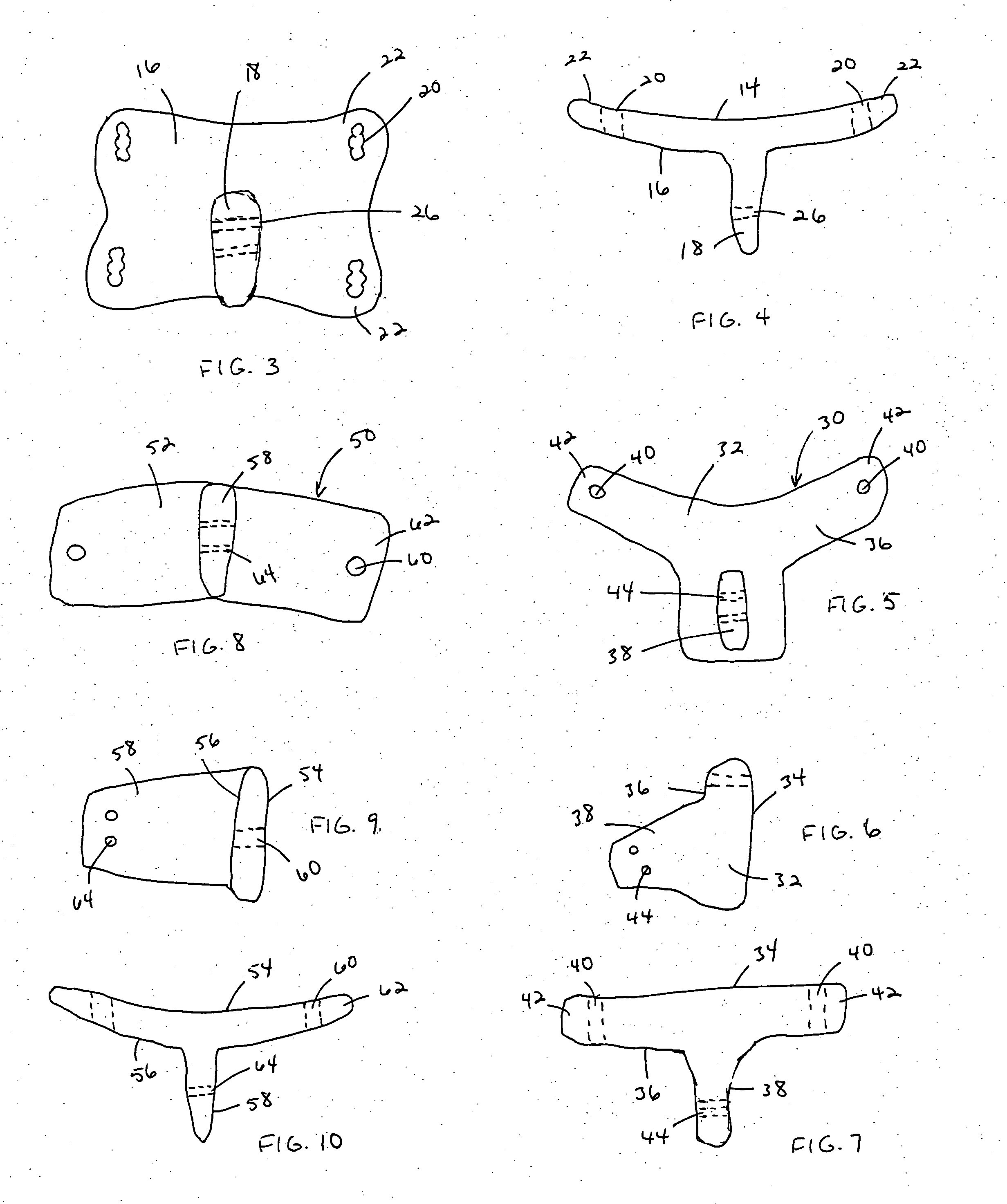
[0034] As representatively illustrated in FIGS. 1-4, the present invention is directed to a spinal implant device, generally designated by the reference numeral 10, with a body 12 having a generally planar anterior surface 14 and a corresponding posterior surface 16 from which a projection 18 extends outwardly, the projection being substantially perpendicular to the posterior surface. The planar body 12 has a generally rectangular shape when viewed from the anterior or posterior sides, and typically includes a plurality of through-passing apertures 20 located in distal or corner portions 22 thereof for receiving fastening members 24. The apertures may provide for variable positioning of the fastening members as shown in FIG. 3, or may be generally circular for a single position. The posterior projection 18 is provided with a plurality of suture holes 26 for anchoring muscles and ligaments to the posterior projection 18.

[0035] As shown, the embodiment set forth in FIGS. 1-4 has four...

second embodiment

[0036] the spinal implant device according to the present invention, generally designated by the reference numeral 30, is illustrated in FIGS. 5-7. As with the previous embodiments, the device 30 includes a body 32 having a generally planar or gently curved anterior surface 34 and a corresponding posterior surface 36 from which a projection 38 extends outwardly. When viewed from the anterior or posterior sides, the body 32 has a somewhat triangular shape and typically includes at least two through-passing apertures 40 located in distal portions 42 thereof for receiving fastening members (not shown). The posterior projection 38 is provided with a plurality of suture holes 44 for anchoring muscles and ligaments to the posterior projection 38.

[0037] The first and second embodiments are designed for lumbar and thoracic vertebrae, with the four-aperture embodiment of FIGS. 1-4 being used to fuse two vertebrae and the dual-aperture embodiment of FIGS. 5-7 serving to stabilize a single ver...

third embodiment

[0038] the spinal implant device according to the present invention, generally designated by the reference numeral 50, is illustrated in FIGS. 8-10 and is particularly suited for use with cervical vertebrae. As with the previous embodiments, the device 50 includes a body 52 having a generally planar anterior surface 54 and a corresponding posterior surface 56 from which a projection 58 extends outwardly, generally perpendicular to the posterior surface 56. When viewed from the anterior or posterior surfaces, the body 52 has a generally rectangular shape and typically includes a plurality of apertures 60 located in distal portions 62 thereof for receiving fastening members (not shown). The posterior projection 58 is provided with a plurality of suture holes 64 for anchoring muscles and ligaments to the posterior projection 58.

[0039] In each of the three embodiments, the posterior projection has a shape intended to replicate the spinous process of corresponding vertebrae from which th...


PUM


Abstract

A spinal implant device having an anatomical shape designed to mimic and restore normal human spinal anatomy. The devices comes in a range of sizes and are structured to specifically accommodate the structure of at least one of the cervical, thoracic and lumbar regions of the spine. Once affixed to the vertebrae, the devices may be used to effectively fuse two or more vertebrae, or to stabilize the vertebrae and protect the posterior portions of the spinal cord. Adjustments for sagittal plane contouring may also be effected through cable tensioning via spinous process fixation.

Description

[0001] This application is entitled to and hereby claims the priority of co-pending U.S. Provisional application Ser. No. 60 / 531,684 filed Dec. 23, 2003.BACKGROUND OF THE INVENTION [0002] 1. Field of the Invention [0003] The present invention is related to the field of spinal surgery and, more particularly, to a device for restoring vertebral anatomy at the time of laminectomy or for revision posterior spinal surgery. [0004] 2. Description of the Related Art [0005] Following spinal fusion surgery, patients often experience difficulty due to post laminectomy instability, decompensated lumbar lordosis, transitional syndrome and “fusion disease”. Accordingly, a need exists for a device that is able to restore vertebral anatomy at the time of laminectomy or for revision posterior spinal surgery. SUMMARY OF THE INVENTION [0006] In view of the foregoing, one object of the present invention is to overcome the difficulties associated with spinal fusion including post laminectomy instability...

Claims


Application Information

Patent Timeline
IPC IPC(8): A61B17/70
CPCA61B17/7007A61B17/701A61B17/7071A61B17/7059A61B17/7058
Inventor TOZZI, JAMES E.
Owner TOZZI JAMES E
Why Eureka
Try Eureka