Structure for multiple-effect distillation using tubes or plates

a technology of distillation structure and tube or plate, which is applied in the field of modular structure, can solve problems such as difficult maintenance, and achieve the effect of reducing manufacturing costs and increasing product output capacity

Inactive Publication Date: 2005-07-14
STOUT TIMOTHY R
View PDF10 Cites 14 Cited by
  • Summary
  • Abstract
  • Description
  • Claims
  • Application Information

AI Technical Summary

Benefits of technology

[0009] I further disclose a novel method of using plates as heat exchangers, using the new, improved structure. Use of heat exchanger plates can result in reduced manufacturing costs and a denser concentration of heat exchange surface area within a given shell volume, which in turn provides for a higher product output capacity for a given physical equipment size.

Problems solved by technology

While the structure disclosed by the former invention was simple to manufacture, it proved difficult to maintain.

Method used


Image

  • Structure for multiple-effect distillation using tubes or plates
  • Structure for multiple-effect distillation using tubes or plates
  • Structure for multiple-effect distillation using tubes or plates

Examples


third embodiment

[0033]FIG. 4 illustrates a vapor-tight chamber 10, this embodiment featuring a cylindrical shell 380 instead of a rectangular shell 240 as in the previous embodiments. Cylindrical shell 380 comprises a fixed shell segment 382 and a removable shell segment 384; together they provide complete external, axial containment of vapor-tight chamber 10.

[0034] Removable shell segment 384 overlaps fixed shell segment 382 sufficiently to provide a sealing surface 386 and a fastening region 388, fastening region 388 provides apertures 390 for the passage of bolts 392 fastened (stud welding preferred to minimize leakage potential) to fixed shell segment 382. Nuts 394 are inserted on bolts 392 and tightened in order to sealingly secure removable shell segment 384 to fixed shell segment 382. A gasket 396 may be used to effect the seal.

[0035] Cylindrical shell 380 typically extends over a multiplicity of effects, and is divided into a series of cylindrical containment boxes 400, such that that port...

first embodiment

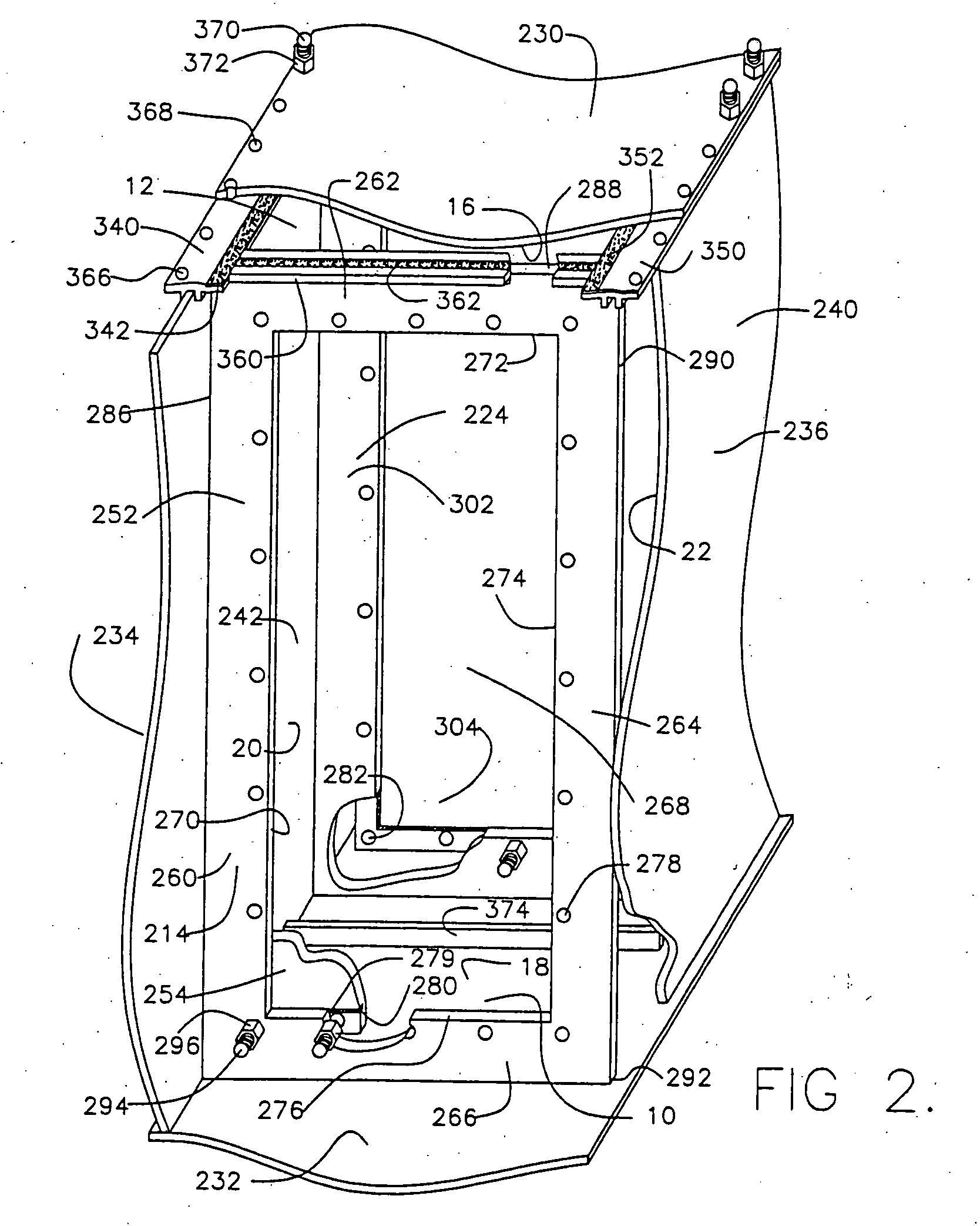
[0049]FIG. 7 corresponds to FIG. 6, which showed the prior invention for reference, but shows the improvements of this invention.

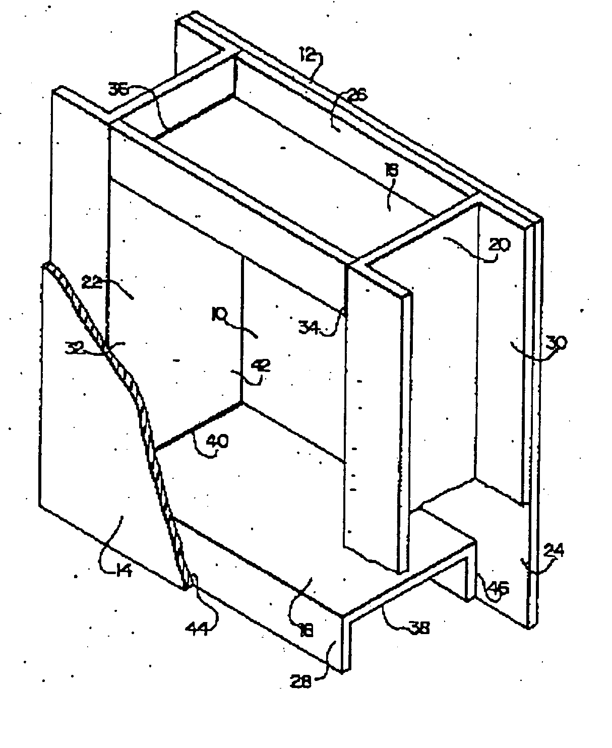
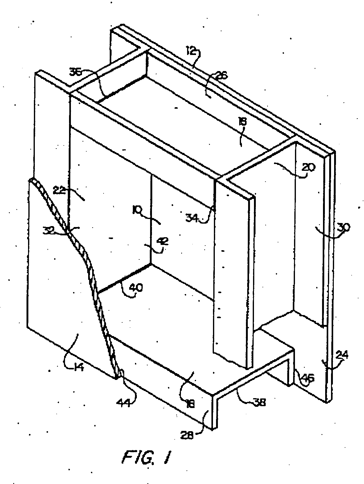
[0050] A vapor-tight chamber 10 of effect module 12 is bounded by containment box 242, by compound baffle assembly 214 located at first end 44 of containment box 242, and by adjacent compound baffle assembly 224 located at second end 46 of containment box 242, with containment box 242 comprising a portion of top plate 230 and a portion of bottom plate 232 and beginning at first end 44 and ending at second end 46. Compound baffle assembly 214 comprises mounting baffle 242 and removable baffle 254. Adjacent compound baffle assembly 224 comprises adjacent mounting baffle 302 and adjacent removable baffle 304.

second embodiment

[0051] In FIG. 7, the adjacent compound baffle assembly 224 sealingly joins top plate 230 of containment box 242 by flange 360 and gasket 362 at second end 46. Since the still works under a vacuum, the forces of the external, ambient atmospheric pressure will keep top plate 230 pressed tightly against sealing gasket 362. The bottom portion of adjacent compound baffle 224 provides an example of the shell as disclosed in FIG. 3, wherein adjacent removable baffle 304 extends directly to bottom plate 232 and seals against it with gasket 500.

[0052] Similarly, compound baffle assembly 214 sealingly joins top plate 230 of containment box 242 by flange 360 and gasket 362 at first end 44. The bottom portion of compound baffle 214 provides an example of the first embodiment of the shell as disclosed in FIG. 2, wherein adjacent removable baffle 304 is sealingly fastened to mounting baffle 302 which in turn is rigidly, sealingly joined to bottom plate 232.

[0053] Aperture 62 is provided in adja...


PUM


Abstract

A structure for a multiple-effect still includes a horizontal shell encompassing a plurality of effects and a series of vertical compound baffles fastened to the horizontal shell and dividing it into a series of pressure-tight chambers. Each chamber along with its associated apparatus constitutes an effect. Each compound baffle comprises a fixed baffle and a removable baffle. A heat exchanger is fastened to the removable baffle and includes an evaporation surface, a condensation surface, and a pressure chamber isolated from the pressure-tight chamber in which it is located. A port in the compound baffle allows evaporate to pass between the pressure chamber and the pressure-tight chamber of an adjacent effect. The shell is provided with a removable top plate to provide access to the heat exchanger and allow removal of the heat exchanger and removable baffle.

Description

CROSS-REFERENCE TO RELATED APPLICATIONS [0001] The present patent application is a nationalization of International application No. PCT / US2003 / 005805, filed Sep. 27, 2003, published in English, which is based on, and claims priority from, U.S. provisional Application No. 60 / 361,197, filed Mar. 2, 2002, both of which are incorporated herein by reference in their entireties.BACKGROUND OF THE INVENTION [0002] 1. Field of the Invention [0003] This invention relates to an improved structure for multiple-effect distillation. More specifically, it relates to a modular structure for each effect, wherein a multiplicity of modules are concatenated to produce the desired number of effects. It is applicable to effects using either tubes or plates as the primary heat exchanger between effects. [0004] 2. Related Art [0005] This is an improvement invention on my U.S. Pat. No. 5,423,759, Structure for multiple-effect distillation, which disclosed a structure for a multiple-effect still based on sin...

Claims


Application Information

Patent Timeline
Patent Type & Authority Applications(United States)
IPC IPC(8): A61M5/175B01D3/06
CPCB01D3/065Y10S159/42Y10S159/08
Inventor STOUT, TIMOTHY R.
Owner STOUT TIMOTHY R
Why Eureka
Try Eureka