Extreme ultraviolet source

a technology of ultraviolet light and source, which is applied in the field of ultraviolet light sources, can solve the problems of reducing the conversion efficiency of electrical energy into euv radiation energy in the desired wavelength range, narrowing of the area of the plasma with an optimum parameter range, and narrowing of the conversion efficiency, so as to increase the conversion efficiency of electrical energy and increase the output of euv radiation

Inactive Publication Date: 2005-07-14
USHIO DENKI KK
View PDF9 Cites 37 Cited by
  • Summary
  • Abstract
  • Description
  • Claims
  • Application Information

AI Technical Summary

Benefits of technology

[0027] The invention was devised to eliminate the above described disadvantage in the prior art. Thus, a primary object of the invention is to make the initial density within the discharge tube uniform in space in an EUV source in which EUV radiation is produced by a high temperature plasma which results from a discharge, and thus, both to increase the conversion efficiency of the electrical energy into EUV radiation energy and also to increase the output of EUV radiation.

Problems solved by technology

If, in the arrangement of the discharge part shown in FIG. 4, the gradient of the initial gas pressure in the discharge space is large in the direction of the optical axis, the problem arises that the efficiency of the conversion of input electrical energy into EUV radiation energy in the desired wavelength range (hereinafter, also called only conversion efficiency) decreases.
However, if the initial gas pressure has a gradient and if the initial gas density is nonuniform in space, the temperature and the density of the plasma which has been heated by the discharge become nonuniform in space and the area of the plasma which has an optimum parameter range becomes narrow.
As a result, the conversion efficiency is reduced.
Here, the disadvantage arises that EUV radiation emergence with the required magnitude cannot be achieved.
As was described above, in the arrangement of the discharge part in the prior art, it is difficult to achieve both an increase in conversion efficiency and also an increase of light intensity at the same time.

Method used


Image

  • Extreme ultraviolet source
  • Extreme ultraviolet source
  • Extreme ultraviolet source

Examples


Embodiment Construction

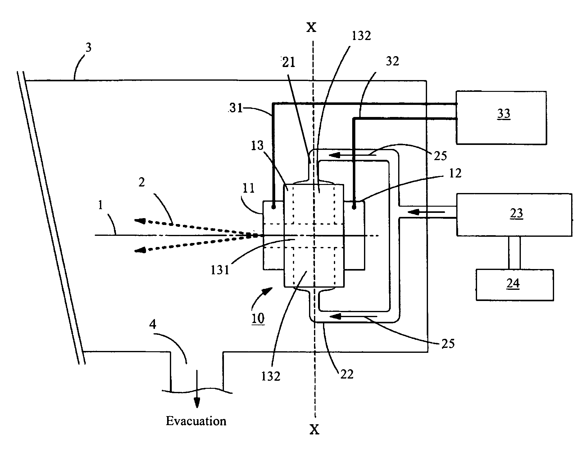
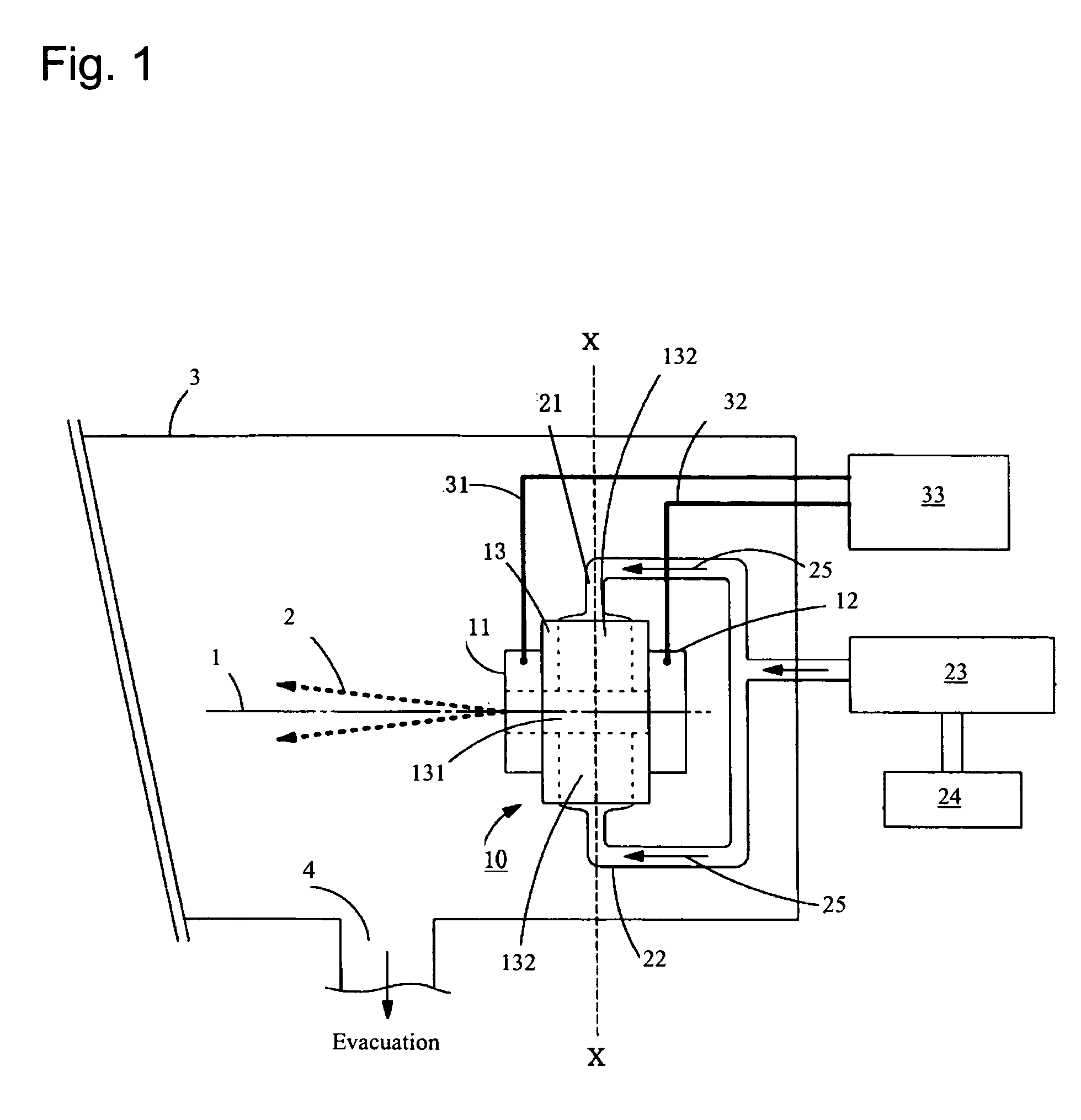
[0043]FIG. 1 shows a schematic of an EUV source according to one embodiment of the invention having a vessel 3 which can be vacuum-evacuated. In the vessel 3, there is a discharge module 10 in which a discharge tube 13, as an insulator, is clamped between an anode 11 which serves as a first electrode and a cathode 12 which serves as a second electrode. The anode 11 and the discharge tube 13 each have a central through-opening. The center axes of these through-openings are aligned with another and form an optical axis 1. Furthermore, the through opening of the discharge tube 13 forms a discharge space 131. The cathode 12 does not have a through opening. The end on the cathode side of the discharge space 131 of the discharge tube 13 is sealed by the cathode 12. In the discharge tube 13, in the radial direction with respect to the optical axis 1, there is a gas supply space 132 for supply of the discharge gas and it has access to the discharge space 131. The gas supply space 132, in th...


PUM


Abstract

To both increase the efficiency of conversion into EUV radiation energy and also increase the amount of emerging EUV radiation in an EUV source a discharge tube is connected to a gas supply space for supply of the discharge gas which in located radially with respect to an optical axis. The discharge gas is supplied to the discharge space through the gas supply space, passes through the center opening of the anode, emerges from the discharge part and is afterwards evacuated from an evacuation opening. The anode and the cathode are connected to a pulse current source. Discharge plasma is produced and EUV radiation is formed by a heavy current pulse from the pulse current source within the discharge space of the discharge tube. The EUV radiation which has formed passes through a through-opening of the anode and is emitted to the outside.

Description

BACKGROUND OF THE INVENTION [0001] 1. Field of Invention [0002] The invention relates to an EUV source (EUV=extreme ultraviolet) in which EUV radiation is produced by a high temperature plasma which has been produced by a discharge, such as, for example, an EUV source which is used for a semiconductor lithography device, bioanalysis, material structural analysis, or the like. [0003] 2. Description of Related Art [0004] An EUV source of the so-called Z-pinch type as is described, for example, in Japanese patent disclosure document JP-A-2002-507832 (and corresponding U.S. Pat. No. 6,075,838), is known as a light source which is used for semiconductor lithography or the like and in which EUV radiation with a wavelength from roughly 10 nm to 15 nm is produced. Here, the following takes place: [0005] an emission gas such as xenon gas or the like is introduced into the space between the anode and the cathode; [0006] afterwards, an electrical pulse with high energy is applied between the a...

Claims


Application Information

Patent Timeline
Patent Type & Authority Applications(United States)
IPC IPC(8): H01L21/027H05G2/00
CPCH05G2/003
Inventor SATO, HIROTOBESSHO, KAZUNORITERAMOTO, YUSUKEYAMATANI, DAIKI
Owner USHIO DENKI KK
Why Eureka
Try Eureka