Fluorescent detector with automatic changing filters

a technology of fluorescent detectors and filters, applied in the direction of fluorescence/phosphorescence, luminescent dosimeters, optical radiation measurement, etc., can solve the problems of limited microscopy systems, unsuitable quantitative measurements such as concentration measurements, and limited viewing of microscopy systems

Active Publication Date: 2005-07-14
APPL BIOSYSTEMS INC
View PDF14 Cites 63 Cited by
  • Summary
  • Abstract
  • Description
  • Claims
  • Application Information

AI Technical Summary

Problems solved by technology

However, microscopy systems are limited to viewing only one depth of view of the sample at a time, and thus, are unsuitable for making quantitative measurements, such as a concentration measurement.
However, microscopy systems are limited to viewing only one depth of field plane at a time.

Method used


Image

  • Fluorescent detector with automatic changing filters
  • Fluorescent detector with automatic changing filters
  • Fluorescent detector with automatic changing filters

Examples


Embodiment Construction

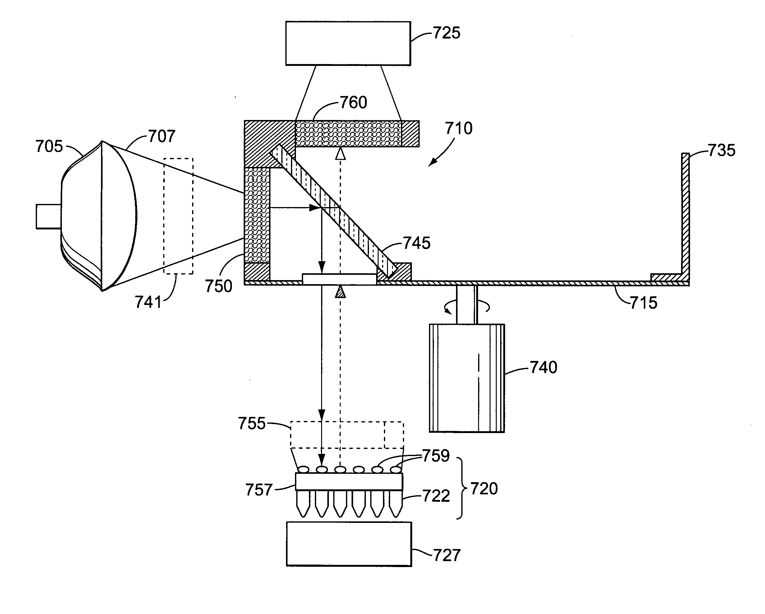
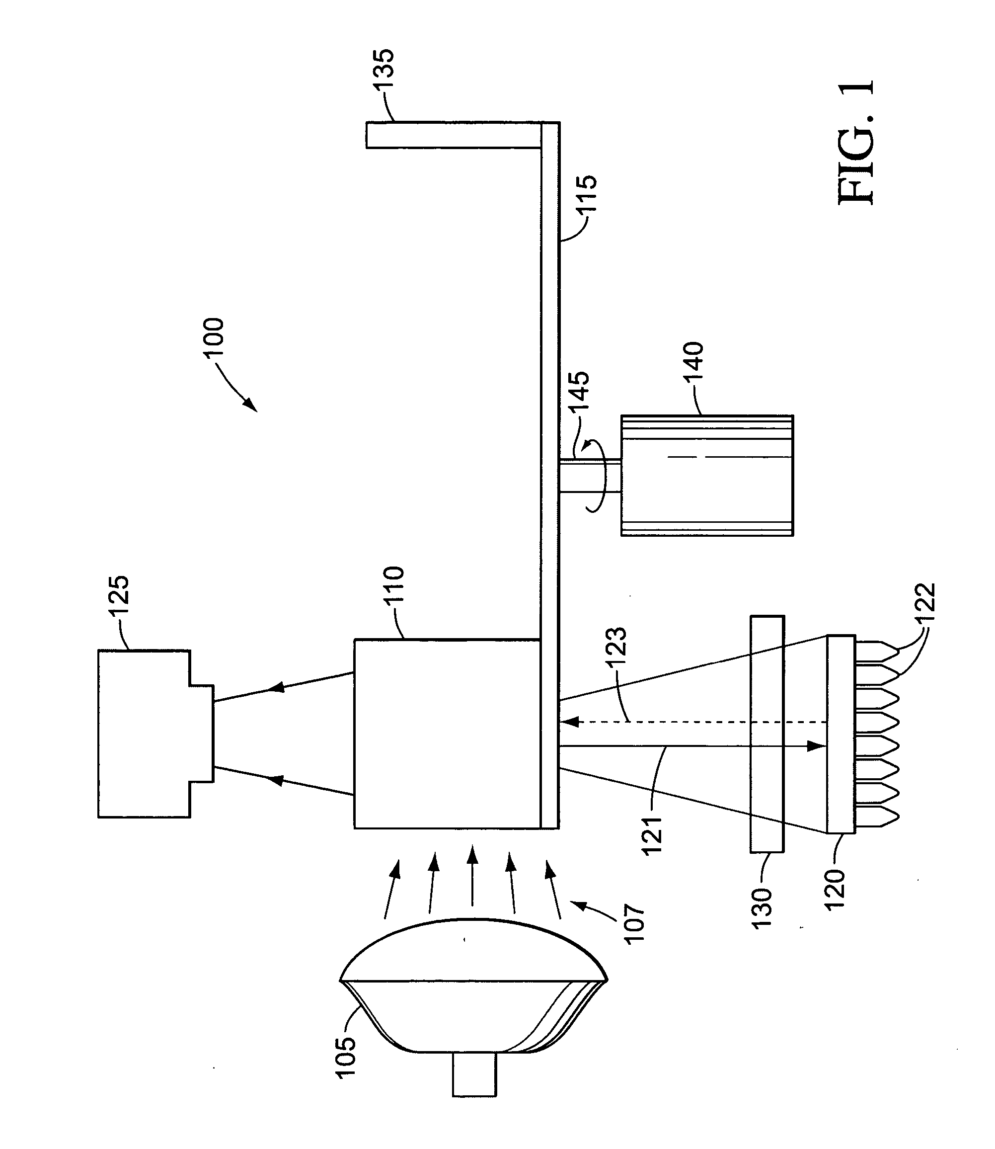
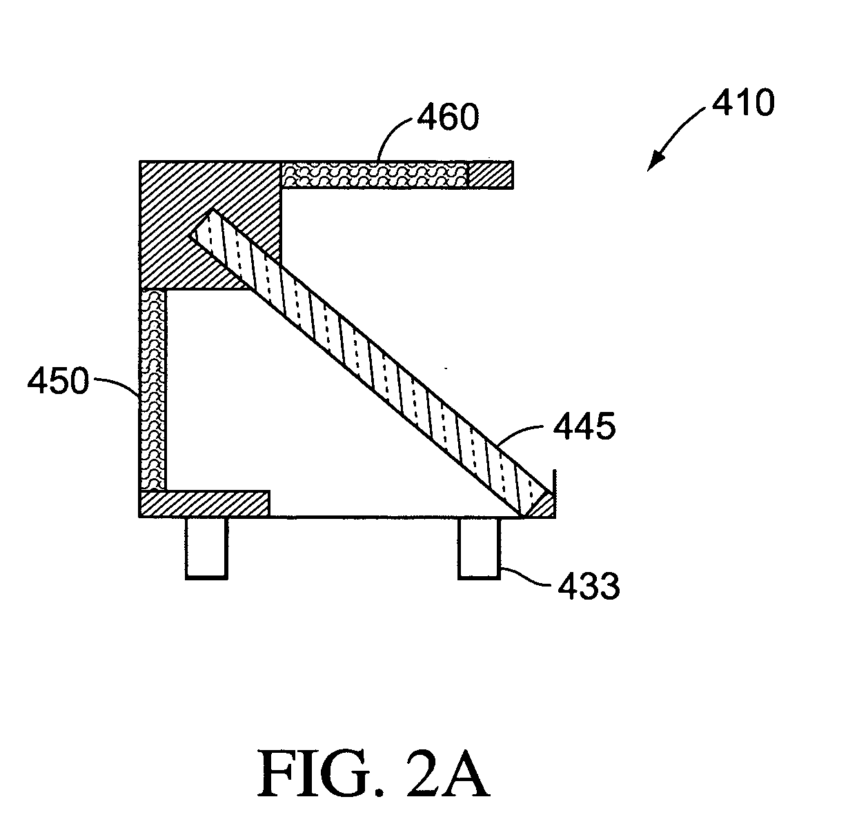
[0019] Reference will now be made in detail to some embodiments of the invention, examples of which are illustrated in the accompanying drawings. Wherever possible, the same reference numbers will be used throughout the drawings to refer to the same or like parts.

[0020] The term “light source” as used herein refers to a source of photons that can provide excitation that results in fluorescent emission. Light sources can include, but are not limited to, white light, halogen lamps, lasers, solid state lasers, laser diodes, micro-wire lasers, diode solid state lasers (DSSL), vertical-cavity surface-emitting lasers (VCSEL), LEDs, phosphor coated LEDs, organic LEDs (OLED), thin-film electroluminescent devices (TFELD), phosphorescent OLEDs (PHOLED), inorganic-organic LEDs, LEDs using quantum dot technology, LED arrays, an ensemble of LEDs, floodlight systems using LEDs, and / or white LEDs, filament lamps, arc lamps, gas lamps, and fluorescent tubes. Light sources can have high radiance, s...


PUM

PropertyMeasurementUnit
excitation wavelengthaaaaaaaaaa
anglesaaaaaaaaaa

Abstract

A fluorometry device and method adapted to determine concentration of spectrally distinguishable species in a biological sample with a plurality of movable optical devices.

Description

FIELD [0001] The present teaching related to methods and systems for fluorescent detection in biological samples. INTRODUCTION [0002] Polymerase chain reaction (PCR) is a process for amplifying or multiplying quantities of double-stranded deoxyribonucleic acid (DNA) in a sample. Measurements can be taken, in situ, to monitor the performance of the PCR process. One measurement technique is microscopy. Microscopy can be used to spatially resolve features of interest in the DNA content of the sample based on dyes that fluoresce in the presence of DNA. However, microscopy systems are limited to viewing only one depth of view of the sample at a time, and thus, are unsuitable for making quantitative measurements, such as a concentration measurement. To resolve different features, microscopy systems use collimating lenses to collimate the light reaching the sample and to collimate the light reaching the detector. Collimated light permits information about the spatial content from one depth...

Claims


Application Information

Patent Timeline
Patent Type & Authority Applications(United States)
IPC IPC(8): G01N21/25G01N21/64
CPCG01N21/253G01N21/6452G01N2021/6439G01N2201/0245G01N2021/6476G01N2021/6478G01N2021/6471
Inventor BOEGE, STEVEN J.HOSHIZAKI, JON A.OLDHAM, MARK F.ILKOVA, LIANA
Owner APPL BIOSYSTEMS INC
Why Eureka
Try Eureka