Fluorescent microscope

a fluorescent microscope and microscope technology, applied in the field of fluorescence microscopes, can solve the problems of insufficient observation light amount and inability to be easily handled, and achieve the effect of reducing specimen fading and saving power

Inactive Publication Date: 2005-07-14
OLYMPUS CORP
View PDF5 Cites 57 Cited by
  • Summary
  • Abstract
  • Description
  • Claims
  • Application Information

AI Technical Summary

Benefits of technology

[0012] The present invention provides a fluorescent microscope which can reduce the fading of a specimen due to unnecessary irradiation of excitation light and which can achieve power saving as well.

Problems solved by technology

The fluorescent microscope as described above requires space to mount various filters, and these light sources of the illumination light are large and generate large amount of heat, and thus are not easily handled.
On the other hand, in the fluorescence observation by the fluorescent microscope, because a sample is used which has been dyed in advance with various kinds of fluorescent dyes, an observation light amount is not sufficient due to deterioration of the fluorescent dyes over time which is so-called fading.

Method used


Image

  • Fluorescent microscope
  • Fluorescent microscope
  • Fluorescent microscope

Examples


first embodiment

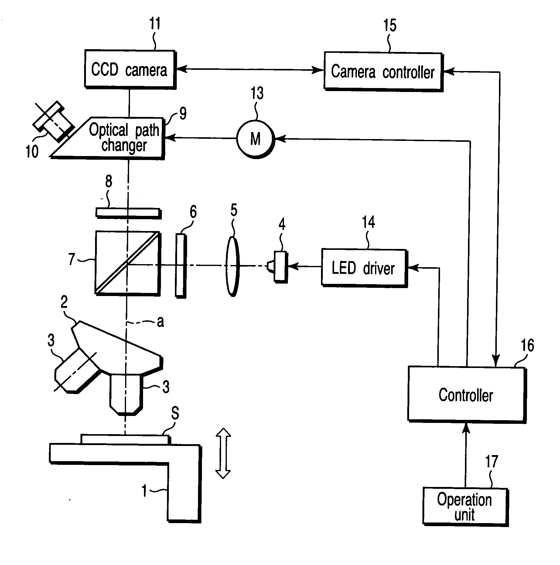
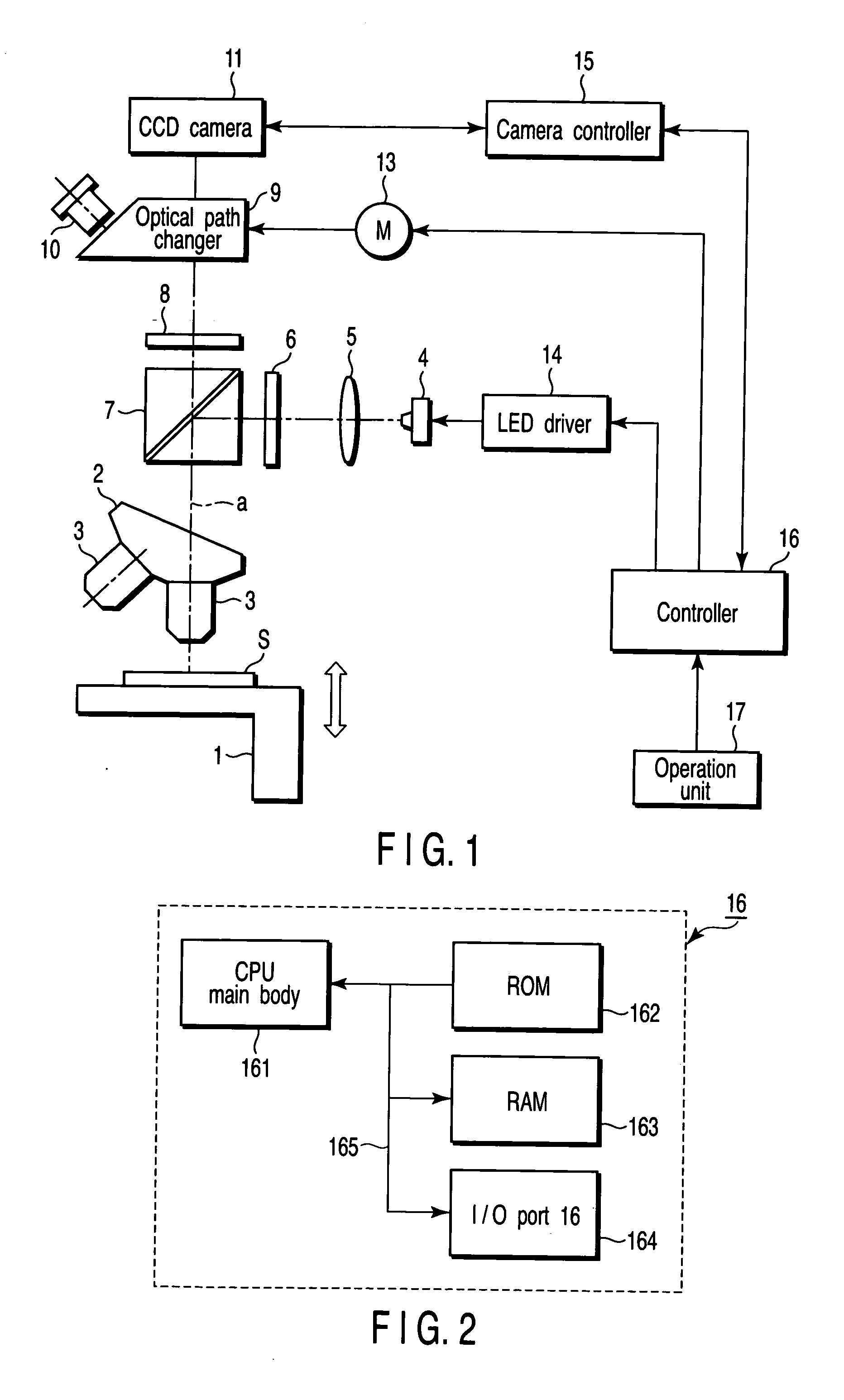
[0024]FIG. 1 is a diagram showing a schematic configuration of a fluorescent microscope according to a first embodiment of the present invention.

[0025] In FIG. 1, a specimen S is mounted on a stage 1. The stage 1 is capable of vertical movement in an optical axis direction (arrow direction indicated in the drawing) so that the specimen S can be focused on.

[0026] An objective lens 3 is disposed above the stage 1 in proximity to the specimen S. A plurality of objective lenses 3 (only two of them are shown in the drawing) with different magnifications is held to a revolver 2, and the desired objective lens 3 is selectively positioned on an observation optical path a by the operation of the revolver 2.

[0027] A collector lens 5 and an excitation filter 6 that configure an illumination optical system are disposed on an optical path of light emitted from an LED 4 as a small light emitting element which is an illumination light source. The collector lens 5 converts the light from the LED...

second embodiment

[0064] A second embodiment of the present invention will be described referring to FIG. 6.

[0065]FIG. 6 is a diagram showing a schematic configuration of the fluorescent microscope according to a second embodiment of the present invention, in which the same signs are given to the same parts as those in FIG. 1.

[0066] The second embodiment is different from the first embodiment in that a transmitted illumination system as illumination means is added in addition to the LED 4 used for the fluorescence observation. In FIG. 6, a mercury lamp, a halogen lamp or the like is used for a transmitted illumination light source 21 as a second light source.

[0067] A transmitted illumination collector lens 22 and a reflection mirror 23 are disposed on an optical path of light emitted from the transmitted illumination light source 21. The transmitted illumination collector lens 22 converts the light from the transmitted illumination light source 21 into parallel light. The reflection mirror 23 refl...

third embodiment

[0074] A third embodiment of the present invention will next be described.

[0075] The third embodiment is concerned with light out timing of the LED 4 which performs the excitation light illumination. The LED 4 lights out at the moment of photography by the CCD camera 11 in the first and second embodiments, but the third embodiment is applied to the case where the observer performs the fluorescence observation with the naked eye via the eyepiece 10. If the excitation light illuminated during observation is blocked each time the observer is not looking through the eyepiece 10, that is, each time the observation is discontinued, fading of the specimen can be reduced. However, in effect, when the observation is frequently continued / discontinued repetitively, it requires time and labor if a light out switch on the control unit 17 is operated to light out the LED 4 each time, and therefore, the excitation light is often illuminated continuously. Moreover, the observer might forget to blo...


PUM


Abstract

A fluorescent microscope has a light source having a small light emitting element, an illumination optical system which leads light from the light source onto a specimen, an observation optical system to which fluorescence emitted from the specimen is led, an imager which images the fluorescence led to the observation optical system, and a controller which controls lighting / light out of the small light emitting element synchronously with imaging timing of the imager.

Description

CROSS-REFERENCE TO RELATED APPLICATIONS [0001] This application is based upon and claims the benefit of priority from prior Japanese Patent Application No. 2004-002887, filed Jan. 8, 2004, the entire contents of which are incorporated herein by reference. BACKGROUND OF THE INVENTION [0002] 1. Field of the Invention [0003] The present invention relates to a fluorescent microscope using small light emitting elements such as a plurality of LEDs as a light source. [0004] 2. Description of the Related Art [0005] Fluorescence observation is widely known in which particular molecules of a biological cell are visualized and distribution of its molecules can be observed. [0006] A fluorescent microscope has been known as a microscope for the fluorescence observation which applies illumination light (excitation light) only having particular wavelength components to a specimen to observe fluorescence produced in the specimen. A mercury lamp, halogen lamp or the like is used as a light source of...

Claims


Application Information

Patent Timeline
Patent Type & Authority Applications(United States)
IPC IPC(8): G02B21/06G02B21/00G02B21/16
CPCG02B21/16
Inventor ENDO, HIDEAKI
Owner OLYMPUS CORP
Why Eureka
Try Eureka