Continuous-range hydrogen sensors

a technology of hydrogen sensors and continuous range, applied in the field of continuous-range hydrogen gas sensors, can solve the problems of limited dimensions and in this embodiment limited

Inactive Publication Date: 2005-07-21
APPLIED NANOTECH HLDG
View PDF30 Cites 27 Cited by
  • Summary
  • Abstract
  • Description
  • Claims
  • Application Information

AI Technical Summary

Benefits of technology

[0007] The present invention provides for novel hydrogen sensors and methods for making same. Generally, such sensors comprise metal alloy nanostructures (wires, particles, films) having nanobreakjunctions that close when exposed to a certain level of hydrogen. Such sensors overcome many of the limi

Problems solved by technology

Dimensions, in this embodiment are limited only by the dimensional limitation

Method used


Image

  • Continuous-range hydrogen sensors
  • Continuous-range hydrogen sensors
  • Continuous-range hydrogen sensors

Examples


example 1

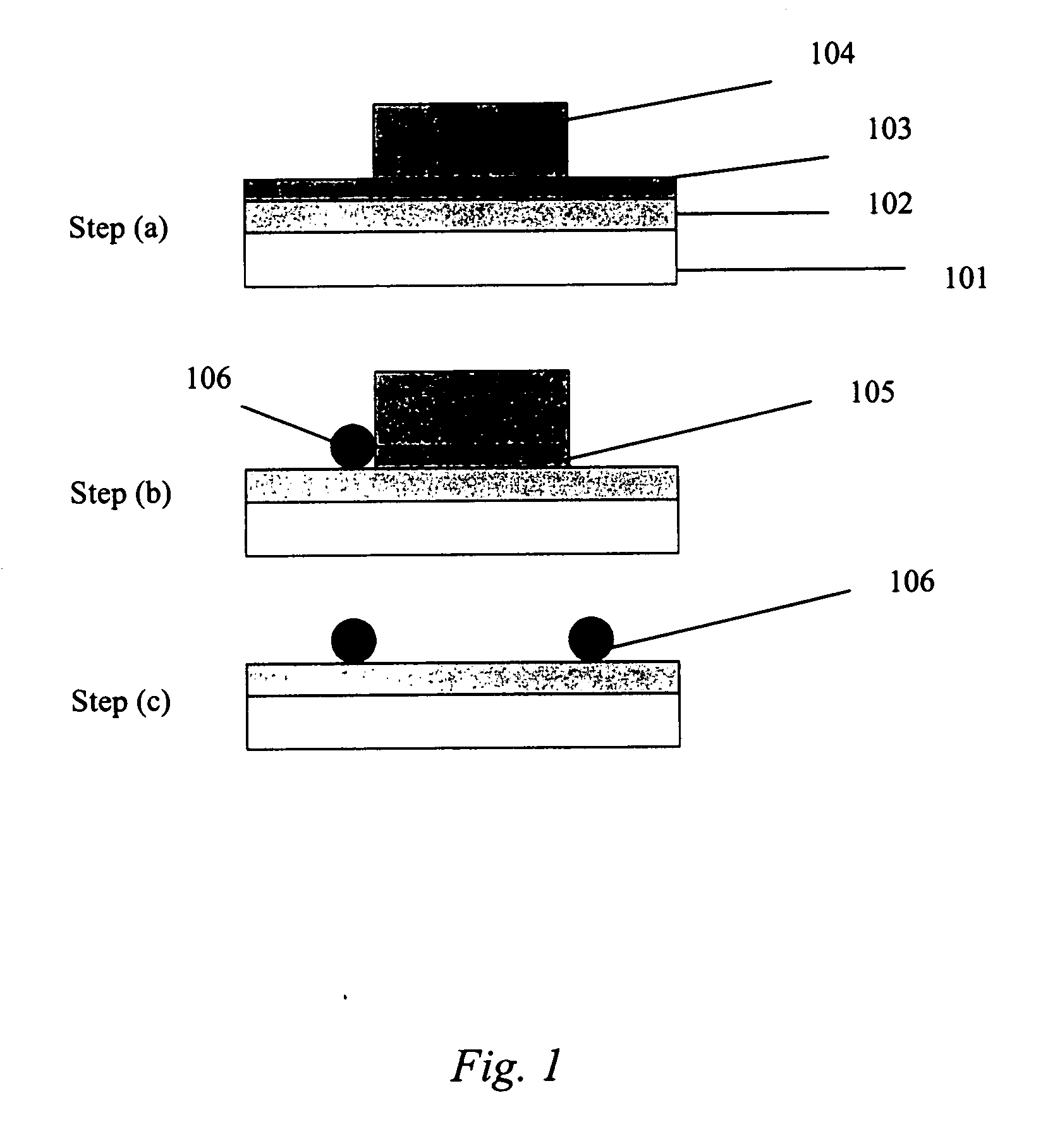
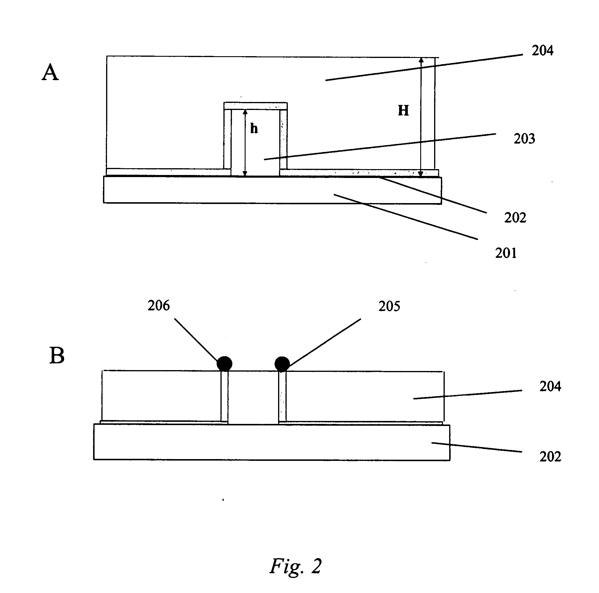
[0058] This example illustrates the electroplating of Pd—Ag nanoparticles onto a patterned substrate to make a continuous-range H2 sensor in accordance with some embodiments of the present invention.

[0059] First, an aqueous Pd—Ag plating bath (solution) was made comprising 2.5 mM PdCl2, 0.5 mM AgNO3, 0.05 M NaNO3, 0.05 M HCl, and 2 M NaCl. The ratio of Pd to Ag in this bath is 5:1. The order in which the bath components are mixed can be important. Accordingly, the components were mixed in the following order: 1) AgNO3→2) NaNO3→3) water→4) HCl (solution should be milky in appearance due to the formation of AgCl)→5) NaCl until the solution becomes clear→6) PdCl2.

[0060] Next, an electroplating process was carried out using chronopotentiometry (constant current process) in a three electrode system to electrochemically deposit nanoparticles onto a patterned Ti substrate. Conditions for electroplating were as follows: −300 μA for 5 seconds (nucleation step), then −20 μA for 450 seconds ...

example 2

[0061] This example illustrates how a continuous-range hydrogen sensor of the present invention can be used in the sensing of hydrogen gas.

[0062] The results of such a sensor measuring the hydrogen concentration dissolved in oil are shown in FIGS. 12A-12D. FIGS. 12A-12D show the response of the hydrogen sensor to hydrogen dissolved in oil at different concentrations (22 ppm, 148 ppm, 419 ppm, 1323 ppm) at room temperature. In all cases the response time of the sensor was around 10 minutes. The same results can be seen when measuring the hydrogen concentration in air, as illustrated in FIGS. 13A and 13B which show the response of a sensor to hydrogen in at different concentrations below the LEL: 2.4-4.4% (FIG. 13A) and 0.7-1.5% (FIG. 13B). The measurements were done at the temperature of 70° C.

example 3

[0063] This example illustrates applications in which the hydrogen sensors of the present invention find utility.

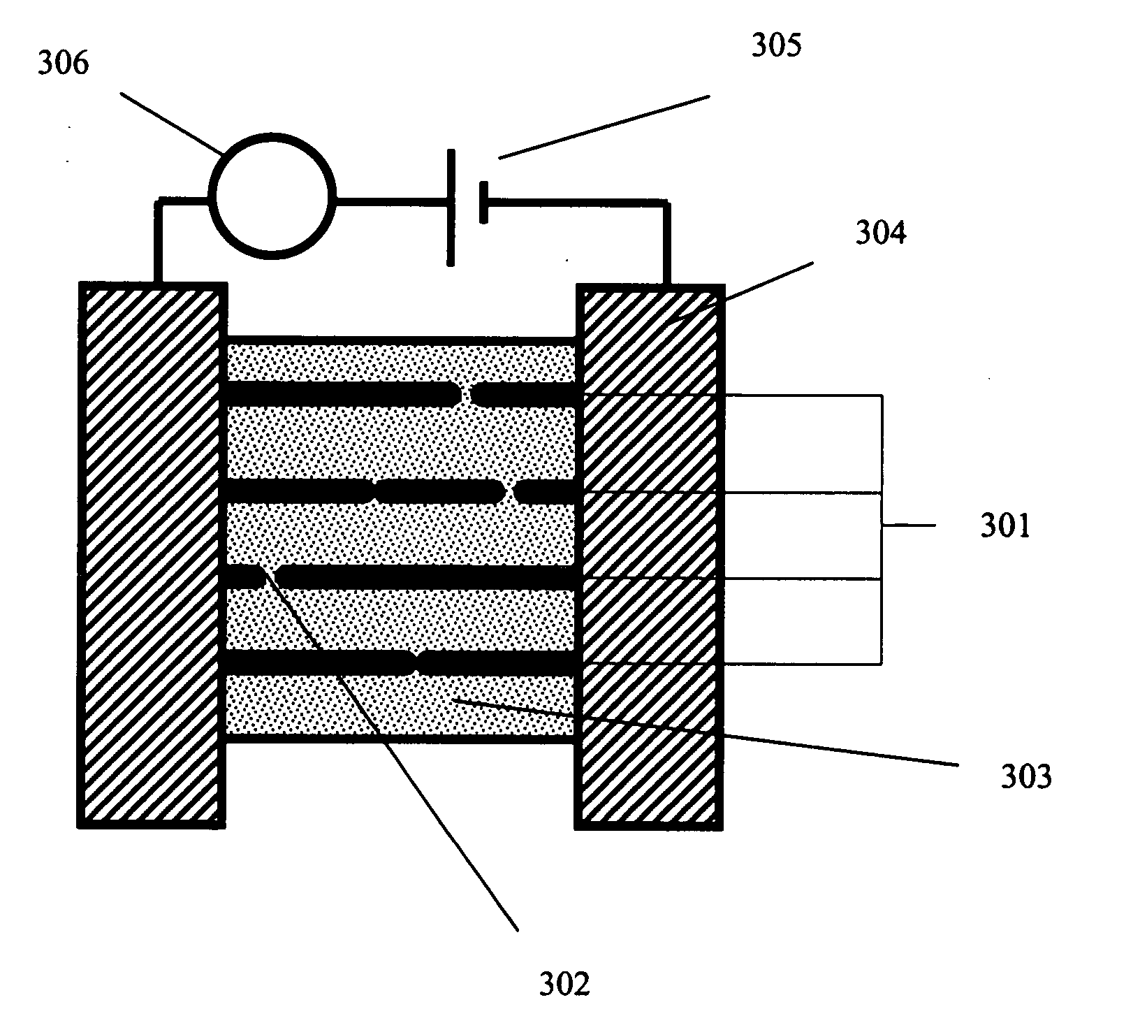
[0064] An exemplary application for such hydrogen sensors is in the monitoring of hydrocarbon breakdown (which leads to the evolution of hydrogen) in transformers. FIG. 14 illustrates a placement of such a sensor 1402 in a transformer 1401 for hydrogen monitoring, wherein electrical contacts 1403 connect the sensing element 1402 (comprising nanowires or columns of metal nanoparticles) to a power supply 1404 and an electrical property monitoring device 1405. In some embodiments, the sensor 1402 is placed in the transformer such that it is exposed to transformer oil. When the filled transformer operation becomes defective, hydrogen and other dissolved gases form in the oil. The sensor 1402 monitors the H2 content dissolved in the oil, helping to identify potential breakdowns and permitting maintenance before such breakdown occurs. Such monitoring can serve to economize the...


PUM


Abstract

The present invention provides for novel hydrogen sensors and methods for making same. In some embodiments, such novel hydrogen sensors are continuous-range hydrogen sensors comprising Pd—Ag nanoparticles arrayed as nanowires or two-dimensional shapes on a resistive surface. Such continuous-range hydrogen sensors are capable of measuring a wide range of hydrogen gas concentration over a wide temperature range. Unlike existing hydrogen sensors that experience a large change in resistance at a certain hydrogen concentration, the continuous-range hydrogen sensor of the present invention changes resistance continuously over a broad range of hydrogen concentration. This continuous change varies slowly with hydrogen concentration and is predictable such that the continuous-range hydrogen sensor can be used to measure hydrogen concentration continuously from a few ppm to 40,000 ppm level or higher over a broad range of temperatures (e.g., −40° C. to +150° C.).

Description

CROSS REFERENCE TO RELATED APPLICATIONS [0001] The present application is a continuation-in-part of the following U.S. patent applications Ser. No. 10 / 854,420, filed May 26, 2004; and Ser. No. 10 / 909,797, filed Jul. 30, 2004.TECHNICAL FIELD [0002] The present invention relates generally to hydrogen sensors, and specifically to continuous range hydrogen gas sensors comprising nanowires and / or arrays of nanoparticles. BACKGROUND INFORMATION [0003] Hydrogen gas (H2) is widely used in industrial and laboratory settings. Because of its high-flamability in air, the need to detect hydrogen gas at levels below its lower explosive limit (LEL is 4% at 25° C.) is of considerable importance. The use of palladium (Pd) as a hydrogen sensor is well-established (F. A. Lewis, “The Palladium Hydrogen System,” Academic Press, New York, 1967) and based on the increased resistance realized when hydrogen dissolves into the metal creating a palladium hydride which has a lower degree of conductivity than p...

Claims


Application Information

Patent Timeline
IPC IPC(8): G01N27/12G01N33/00
CPCG01N33/005G01N27/127
Inventor MONTY, GREGNG, KWOKYANG, MOHSHIFINH, RICHARD
Owner APPLIED NANOTECH HLDG
Why Eureka
Try Eureka