
Seat mounting rail, particularly for a commercial aircraft

a technology for aircraft and seats, applied in the field of seats, can solve the problems of high density, unsatisfactory mechanical characteristics alone, and high cost of titanium alloys, and achieve the effects of avoiding unnecessary weight increase, high strength, and less cos

Active Publication Date: 2005-07-21
AIRBUS OPERATIONS GMBH
View PDF16 Cites 35 Cited by
  • Summary
  • Abstract
  • Description
  • Claims
  • Application Information

AI Technical Summary

Benefits of technology

[0009] to solve the above outlined corrosion problem by a seat mounting rail having excellent mechanical and corrosion resistance characteristics while substantially avoiding the cost and weight problems encountered with rails made entirely of titanium; and
[0015] Making the seat mounting upper section of a titanium alloy has the advantage of solving the corrosion problem without the need for making the entire rail of titanium alloy. Making the lower mounting section of the rail of a high strength aluminum alloy has the advantage of avoiding an unnecessary weight increase. Simultaneously, the seat mounting rails according to the invention are substantially less expensive compared to a seat mounting rail made entirely of a corrosion resistant titanium alloy.

Problems solved by technology

However, it has been found that satisfying mechanical characteristics alone is not entirely satisfactory since other characteristics are also required.
However, titanium alloys are substantially more expensive than aluminum alloys and additionally have a higher density than aluminum alloys which is not advantageous with regard to the constant need for weight reductions in the manufacture of commercial aircraft.
At the same time, the use of seat mounting rails made of titanium alloys makes the floor structure substantially more expensive so that the described solution of the corrosion problem is economically not acceptable.
More specifically, solving the corrosion problem by a titanium seat mounting rail which is about ten times more expensive than a comparable conventional aluminum alloy rail is not acceptable.

Method used


Image

  • Seat mounting rail, particularly for a commercial aircraft
  • Seat mounting rail, particularly for a commercial aircraft
  • Seat mounting rail, particularly for a commercial aircraft

Examples


Embodiment Construction

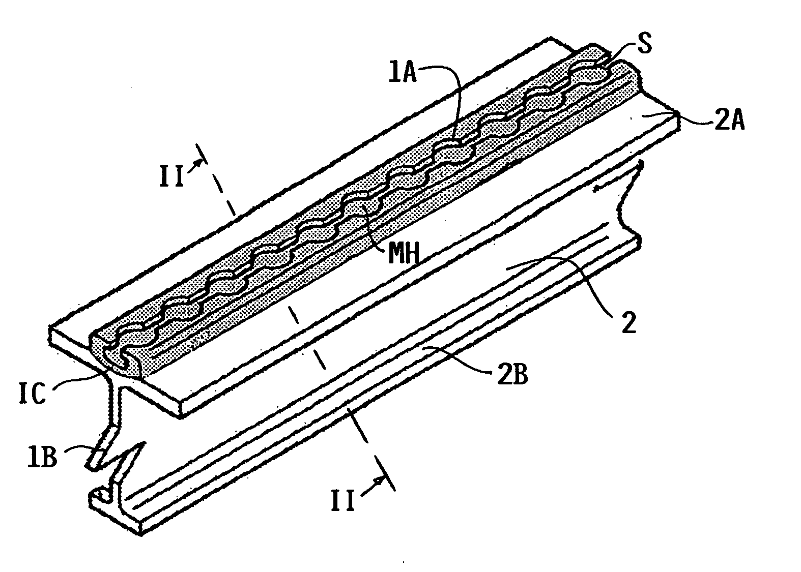
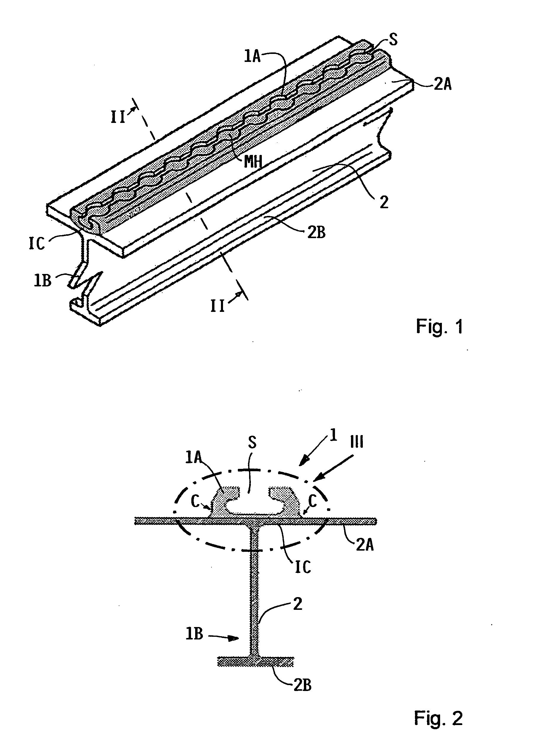
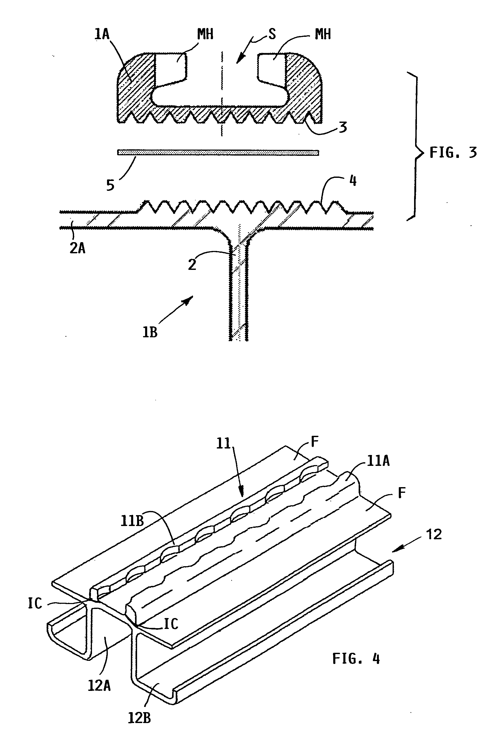
[0022]FIGS. 1 and 2 show a seat mounting rail 1 according to the invention. The rail 1 has an upper seat securing rail section 1A and a lower mounting rail section 1B. The mounting section 1B has a web 2, a top cord 2A and a narrower bottom or foot cord 2B. According to the invention the seat securing upper section 1A is secured to the top cord 2A by a bonding, preferably a metallurgical bond forming an interconnection IC between the upwardly facing surface area of the top cord 2A and the downwardly facing surface area of the upper rail section 1A. The upper rail section 1A has an approximate C-sectional configuration with the open slot S facing upwardly. The open slot S is interrupted at intervals by mounting holes MH. The contact surface area and thus the interconnection area between both sections 1A and 1B may be increased, for example, by forming a crown in one section and a trough in the other section as seen in FIG. 1.

[0023] According to the invention the upper rail section 1...


PUM

PropertyMeasurementUnit
pressureaaaaaaaaaa
weightaaaaaaaaaa
temperatureaaaaaaaaaa

Abstract

A seat mounting rail suitable for mounting passenger seats to a floor, for example an aircraft cabin floor, is divided into an upper section for securing a seat and a lower section for mounting the rail to the floor. The upper section is preferably made of a titanium alloy. The lower section is preferably made of an aluminum alloy. Both sections are connected to each other by an interconnection preferably in the form of a metallurgical bond formed under heat and pressure. A bonding metal foil compatible with the metals of which the rail sections are made is used for enhancing the bonding strength of the interconnection.

Description

PRIORITY CLAIM [0001] This application is based on and claims the priority under 35 U.S.C. §119 of German Patent Application 103 60 809.5, filed on Dec. 19, 2003, the entire disclosure of which is incorporated herein by reference. FIELD OF THE INVENTION [0002] The invention relates to a seat mounting rail for securing passenger seats to the cabin floor of a commercial airliner. Such rails have a lower portion for securing to the floor and an upper portion for securing seats to the rail. Such rails may also be used for securing loads to a floor. BACKGROUND INFORMATION [0003] Mounting rails for securing passenger seats in commercial aircraft are normally standardized. One such standard defining sheets is, for example, air traffic standard LN 29 890. The standard construction of such rails includes a lower mounting rail section having an Ω- or a T-cross-sectional configuration. A chair securing upper rail section includes a C-cross-sectional configuration that opens upwardly into the c...

Claims


Application Information

Patent Timeline
Patent Type & Authority Applications(United States)
IPC IPC(8): B23K20/00B23K20/16B23K20/233B60N2/015B60P7/08B64D11/06
CPCB23K20/00B23K20/16B23K20/2333Y02T50/46B60P7/0815B64D11/0696B60N2/01558Y02T50/40
Inventor VICHNIAKOV, ALEXEIASSLER, HERWIG
Owner AIRBUS OPERATIONS GMBH
Learn More