Transmitting apparatus, receiving apparatus, communication system, transmission method, reception method, and communication method

a technology of transmission apparatus and receiving apparatus, which is applied in the direction of line-transmission details, orthogonal multiplex, multiplex communication, etc., can solve the problems of inability to isolate between channels, clear waste, and inability to modulate and demodulate, so as to improve the efficiency of information transmission

Inactive Publication Date: 2005-07-28
REDWOOD TECHNOLOGIES LLC
View PDF0 Cites 4 Cited by
  • Summary
  • Abstract
  • Description
  • Claims
  • Application Information

AI Technical Summary

Benefits of technology

[0017] The present invention was made in view of the above situation and has as an object to provide a transmitting apparatus, a receiving apparatus, and a communication system comprising a transmitting and receiving apparatus capable of applying a suitable modulation method and transmission path estimation method in accordance with the characteristics of the information to be transmitted and capable of improving the efficiency of the information transmission and signal processing methods for each.
[0033] Further, in the communication system, it is possible to make the modulation method and the transmission path estimation method variable so as to design a transmitting apparatus and receiving apparatus by the smallest limit of the circuit size.

Problems solved by technology

Further, the symbols of the other channels are also necessary for extracting one channel worth of information, so by employing such a data structure isolation between channels is not possible in the modulation method and the transmission path estimation method.
Where handling packet transmission traffic, however, the channels are not always constantly transmitting and receiving signals, therefore with the above system configuration, modulation and demodulation become impossible, so it becomes necessary to perform the modulation and demodulation and the transmission path estimation in a closed state for every channels, that is, for every packet.
This is clearly wasteful from the viewpoint of the effective utilization of the transmission path bandwidth.
The communication system of the prior art, however, has not given sufficient consideration to this.

Method used


Image

  • Transmitting apparatus, receiving apparatus, communication system, transmission method, reception method, and communication method
  • Transmitting apparatus, receiving apparatus, communication system, transmission method, reception method, and communication method
  • Transmitting apparatus, receiving apparatus, communication system, transmission method, reception method, and communication method

Examples


first embodiment

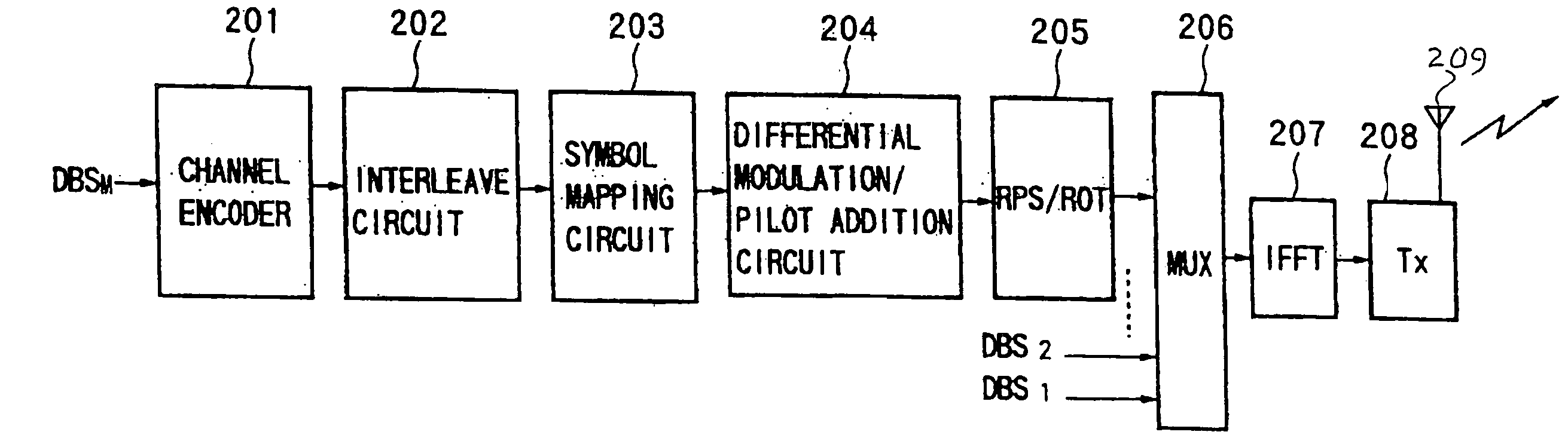
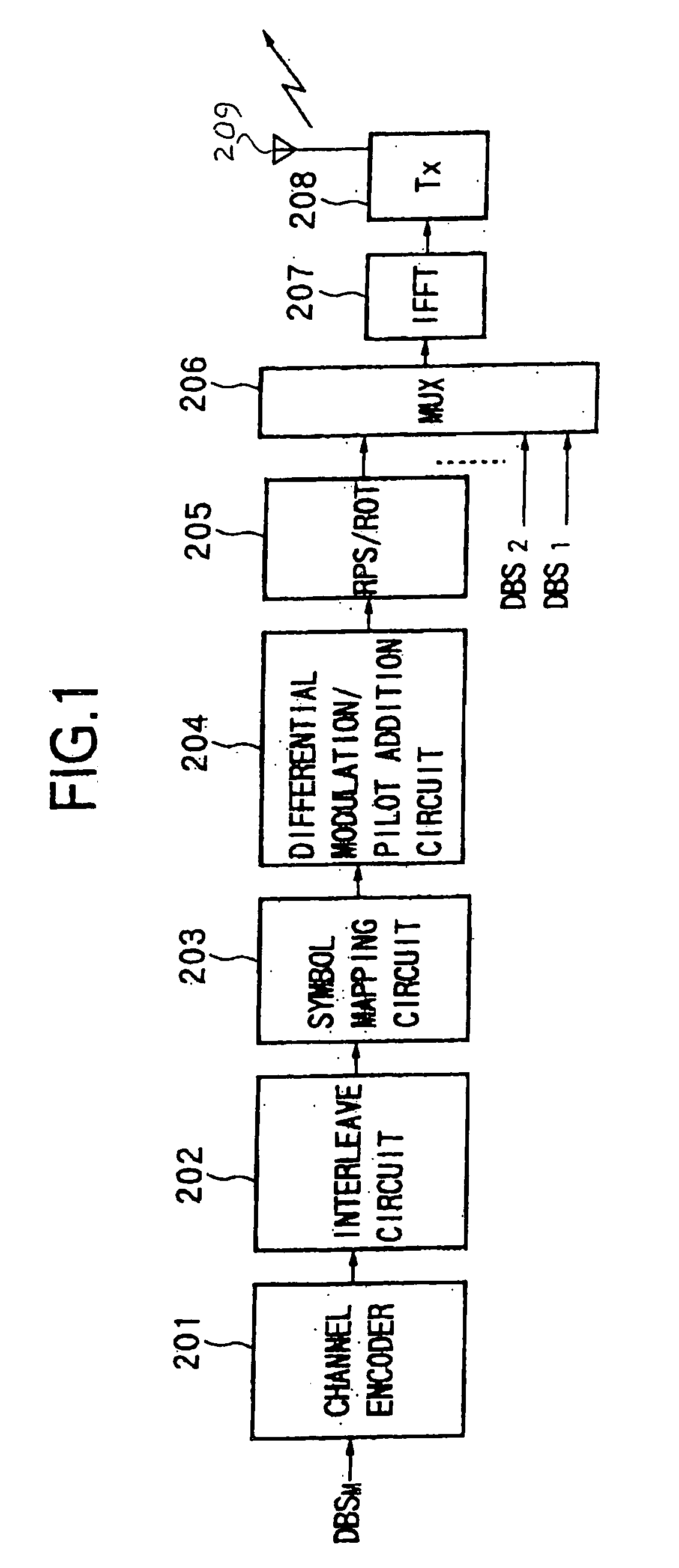
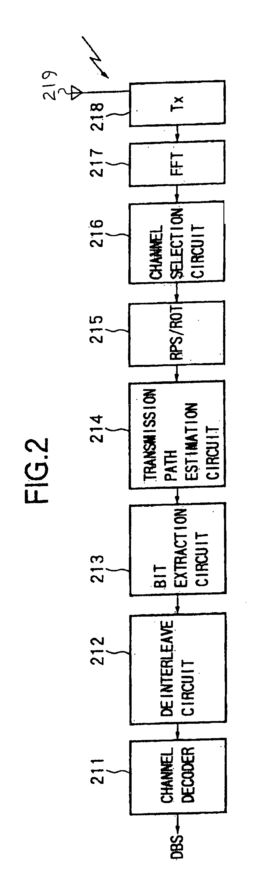
[0058]FIGS. 1 and 2 show a first embodiment according to the present invention, in which FIG. 1 is a block diagram of an example of a configuration of a transmitting apparatus according to the present invention, and FIG. 2 is a block diagram of an example of a configuration of a receiving apparatus according to the present invention.

[0059] As illustrated, the transmitting apparatus of the present embodiment is configured by a channel encoder 201, an interleave circuit 202, a symbol mapping circuit 203, a differential modulation / pilot addition circuit 204, a signal randomization circuit (RPS / ROT) 205, a multiplex circuit (MUX) 206, an inverse fast Fourier transform circuit (IFFT) 207, and a transmission circuit (Tx) 208.

[0060] The channel encoder 201 encodes an input bit stream DBSM of the M channels. Note that the related encoding includes, for example, error correction as well as encoding. The encoded data stream is supplied to the interleaver 202. The interleaver 202 performs int...

second embodiment

[0182]FIG. 18 represents the operation of the present invention and, specifically, the operations of transmission and reception of data in the communication system of the present invention.

[0183] Note that the communication system of the present invention is configured by the transmitting apparatus shown in FIG. 1 and the receiving apparatus shown in FIG. 2. This communication system transfers the data from the transmitting apparatus to the receiving apparatus. Below, an explanation is provided of the operation of the communication system of the present embodiment by referring to FIG. 18.

[0184] The communication system of the present embodiment is a mobile telecommunication system. The transmitting apparatus transmits call information and calls the receiving apparatus as the other party of the communication. When it receives a response from the receiving apparatus and confirms the receiving apparatus, data communication is commenced. Below, a detailed explanation will be made of th...


PUM


Abstract

A transmitting apparatus, receiving apparatus, communication system, and a signal processing method for each apply a suitable modulation method and transmission path estimation method in accordance with the characteristics of the transmission information and capable of improving the transmission efficiency. At the transmission side, the method of estimation of the transmission path and the modulation method are selected in accordance with an attribute of the data to be transmitted, for example, the size of a packet to be transmitted, the transmission data is mapped by the selected modulation method, the signal is processed in accordance with the transmission path estimation method, and a transmission signal is created by increase fast Fourier transform processing and transmitted. At the reception side, the received signal is fast Fourier transformed, the transmission path is estimated by the transmission path estimation method selected at the transmission side, the received signal is corrected in accordance with the result, and the received data is reproduced in accordance with the modulation method. Therefore, it is possible to always adopt the optimum transmission method in accordance with the attribute of the transmission data etc. and possible to realize an improvement of a transmission efficiency and an enhancement of the quality of communication.

Description

BACKGROUND OF THE INVENTION [0001] The present invention relates to a transmitting apparatus and a receiving apparatus of orthogonal frequency division multiplexing (OFDM) modulated signals, a communication system comprising a transmitting apparatus and a receiving apparatus, and further a signal processing method in each of the transmitting apparatus, receiving apparatus, and the communication system. [0002] As a system of transmitting multiplexed channels using multi-carrier communication, a digital audio broadcasting (DAB) system has already been put into practical use in Europe. In the DAB system, OFDM is used as the modulation method. In a broadcasting system using the OFDM modulation method, a plurality of orthogonal sub-carriers modulated by quadrature phase shift keying (QPSK) or quadrature amplitude modulation (QAM) or another data modulation method are multiplexed to produce an OFDM modulated signal. By providing a guard interval which is made by recurring part of an effec...

Claims


Application Information

Patent Timeline
Patent Type & Authority Applications(United States)
IPC IPC(8): H04J11/00H04B3/10H04L27/26
CPCH04L27/2601
Inventor SAKODA, KAZUYUKISUZUKI, MITSUHIRO
Owner REDWOOD TECHNOLOGIES LLC
Why Eureka
Try Eureka