Eureka AIR delivers breakthrough ideas for toughest innovation challenges, trusted by R&D personnel around the world.

Waveguide type optical device and position detecting method,,.

Inactive Publication Date: 2005-07-28
NIKON CORP +1
View PDF7 Cites 0 Cited by
  • Summary
  • Abstract
  • Description
  • Claims
  • Application Information

AI Technical Summary

Problems solved by technology

This principle has, however, a problem that this scheme cannot detect a relative position of the insert plate to the groove and acquire information necessary to determine a static position.
Therefore, there is also a problem that the principle cannot detect secular change of the relative position of the insert plate to the groove that is caused by variation in a mechanical characteristic of the cantilever as a bimetal, deformation of a supporting joint part between the insert plate and the cantilever, etc., and therefore malfunction of the insert plate caused by breakage of the cantilever etc. also cannot be detected.

Method used


Image

  • Waveguide type optical device and position detecting method,,.
  • Waveguide type optical device and position detecting method,,.
  • Waveguide type optical device and position detecting method,,.

Examples


Embodiment Construction

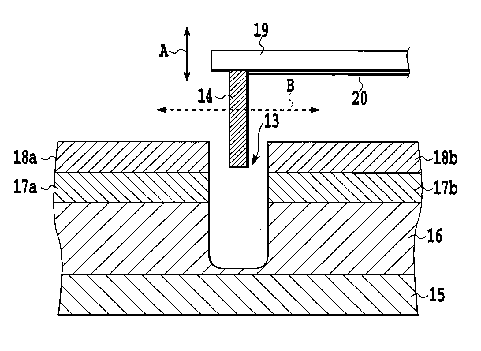
[0028] The embodiments of the present invention will be described in detail below, referring to the drawings. As an example of the waveguide type optical device, an optical switch will be described.

[0029]FIG. 2 shows a configuration of the optical switch according to the one embodiment of the present invention. On a substrate 15, a lower cladding layer 16 and a core layer 17 that will constitute the optical waveguide are deposited successively and subjected to photolithography to form optical waveguides. The lower cladding layer 16 and the core layer 17 are covered with an upper cladding layer 18 to complete the optical waveguide. A groove 13 is provided by removing the core layer 17 and a part of the lower cladding layer 16. A cantilever 19 to which an insert plate 14 is attached at the point thereof is disposed above the groove 13. The cantilever 19 with the insert plate 14 is configured so that the insert plate 14 is movable in a depth direction (indicated by the arrow A) of the...


PUM


Abstract

A waveguide type optical device performs such monitoring as detection of a relative position of an insert plate to a groove. The waveguide type optical device comprises a groove disposed at an intersection position of a first optical waveguide and a second optical waveguide; an insert plate disposed to be insertable into the groove; means for applying a static magnetic field such that a vector product of a velocity vector (A) of the insert plate and its magnetic field vector (B) is nonzero; a cantilever that has electrical wiring including therein a wiring part lying in a direction perpendicular to both the velocity vector and the magnetic field vector and that supports the insert plate; and means for detecting a relative position of the insert plate to the groove by detecting a current induced in the electrical wiring.

Description

TECHNICAL FIELD [0001] This invention relates to a waveguide type optical device and a method for detecting a position, and more specifically to a waveguide type optical device having an insert plate that is disposed to be insertable into a groove used for controlling optical paths of optical waveguides arranged on a substrate, and a position detecting method for detecting a relative position of the insert plate to the groove. BACKGROUND ART [0002] In optical transmission systems, optical switches for changing optical paths to achieve switching of an optical signal are being used in recent years. Especially, the matrix type optical switch for changing optical paths between a plurality of inputs and a plurality of outputs is highly demanded. As a typical matrix type optical switch, there is known an optical switch that switches optical paths by putting a micro mirror constructed by the MEMS (Micro Electro Mechanical Systems) technique into and out of a groove provided between optical...

Claims


Application Information

Patent Timeline
IPC IPC(8): G01D5/353
CPCG01D5/35345G01D5/342
Inventor KURUMADA, KATSUHIKOTAMAMURA, TOSHIAKIKANAYA, MASATOSHINISHI, SHIGENDOAKAGAWA, KEIICHI
Owner NIKON CORP
Why Eureka
Eureka Blog
Learn More