As a result, NA of a projection optical
system of an exposing device is becoming large.
As the required resolution (R) is becoming high, since the K1 factor is becoming low, it becomes difficult to obtain the desired resolution.
Thus, the influence of the dimensional error of a pattern of a photo mask against a transferred pattern is becoming large.
On the other hand, it is very difficult to produce a mask pattern of a photo mask in accordance with its design.
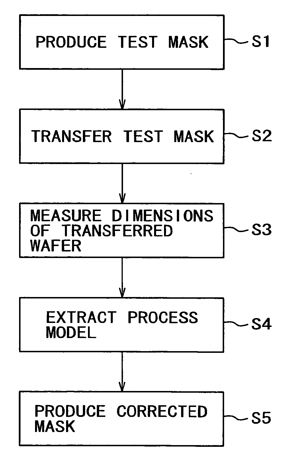
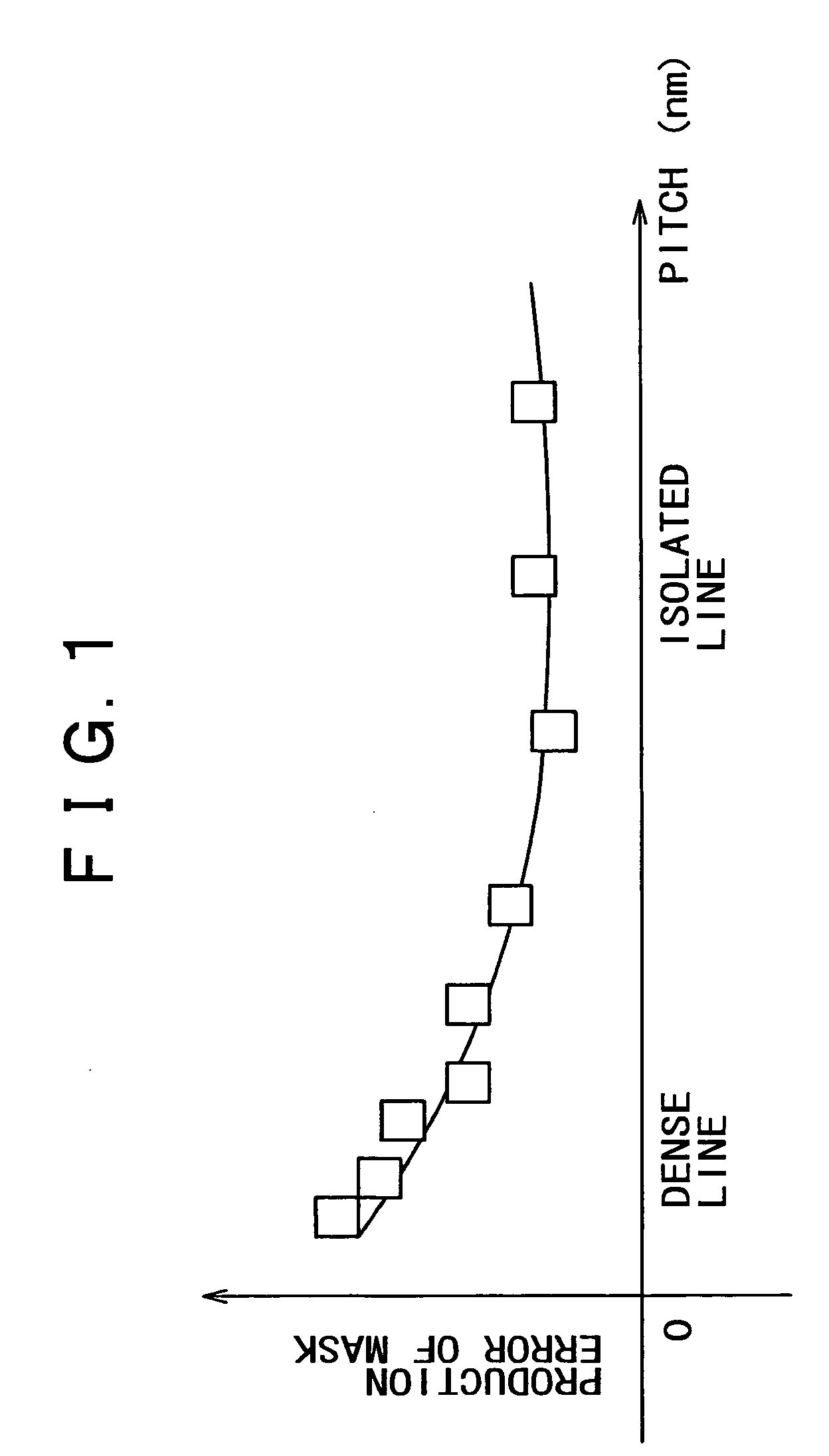
In particular, a problem to be solved is dependency of coarse / dense pattern or an error of
line width depending on coarse / dense pattern..
There is a tendency of which the dimensional error of a pattern of dense lines is larger than the dimensional error of a pattern of isolated lines.
196-204, “Advanced pattern
correction method for fabricating highly accurate reticles”, although the dimensional error of a pattern of a mask mainly results from a drawing error of a mask pattern and an
etching error at an
etching step performed after a patterning step and a developing step have been performed, dimension fluctuating coarse / dense characteristic, namely an error of line width depending on coarse / dense pattern is becoming considered.
However, it is difficult to completely control the error of line width depending on coarse / dense pattern.
However, the error of line width depending on coarse / dense pattern has not been mentioned in a roadmap such as ITRS (International Technology Roadmap for Semiconductors).
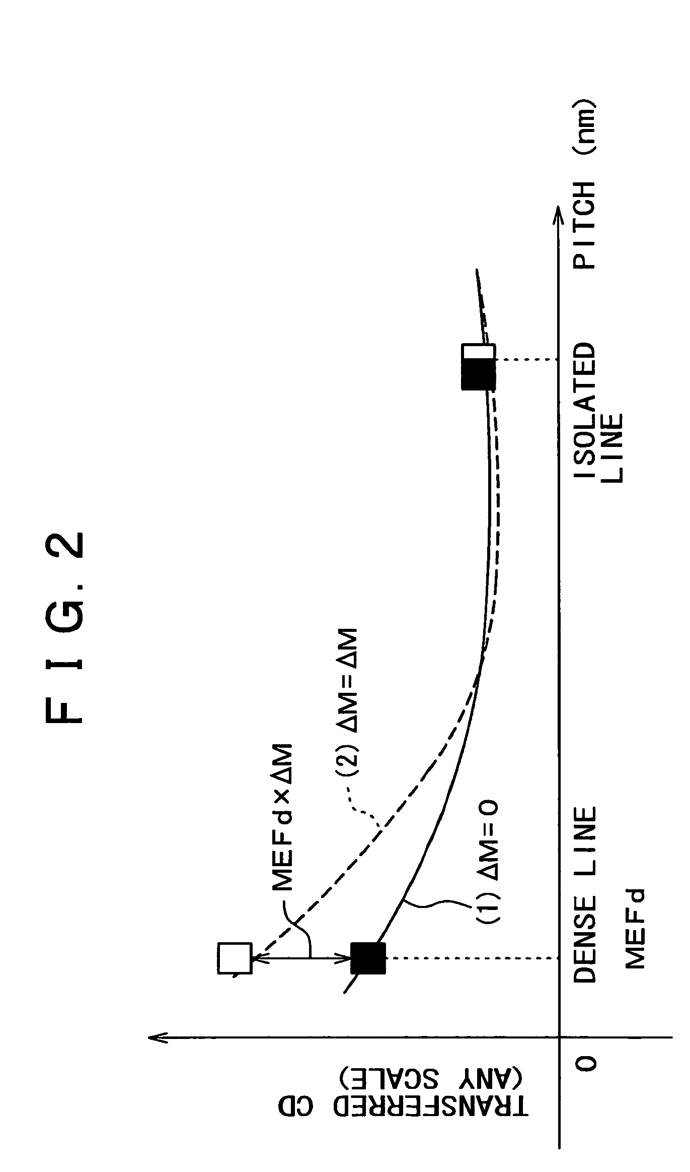
However, as will be described in the following, an error of line width depending on coarse / dense pattern of a mask largely affects a transferred CD error of a transferred pattern.
However, in reality, a mask pattern of a test mask contains an error of line width depending on coarse / dense pattern.
Thus, since a process model that is produced contains a pattern dimension error, an error of line width depending on coarse / dense pattern of a test mask corresponding to an error of line width depending on coarse / dense pattern of a mask is propagated to a process model.
However, in reality, the difference between a test mask and a corrected mask with respect to an error of line width depending on coarse / dense pattern unavoidably takes place in the range of a production error.
As a result, an unignorable error, namely, a mask corrected residual error, takes place in the transferred pattern.
As a result, it becomes difficult to obtain a transferred pattern having a high pattern dimensional control accuracy.
However, in the conventional mask correcting method using the OPC, the difference between masks is not specially considered.
Thus, it becomes difficult to improve the correction accuracy.

