Rotary fast tool servo system and methods

a rotary fast tool and servo technology, applied in the field of rotary fast tool servo system and methods, can solve the problems of insufficient bandwidth for certain manufacturing goals, insufficient speed for certain types of materials to be machined, and linear fast tool servo will produce errors in the desired surface texture, etc., to achieve high bandwidth and precision control, improve accuracy and speed, and improve the effect of speed

Inactive Publication Date: 2005-08-04
MASSACHUSETTS INST OF TECH +1
View PDF37 Cites 18 Cited by
  • Summary
  • Abstract
  • Description
  • Claims
  • Application Information

AI Technical Summary

Benefits of technology

[0006] The present invention is directed to a rotary fast tool servo system that improves the accuracy and speed to enable and meet manufacturing goals for, for example, fabricating three-dimensional surface features. The embodiments of the present invention provide a high level of bandwidth and precision control to form short spatial wavelength features, for example, 50 micron long features with 5 micron peak to valley dimensions at 10 kHz or more. In a preferred embodiment, the rotary fast tool servo system includes a cutting element moun...

Problems solved by technology

However, when the rotary table is positioned so that a component of the reaction force is perpendicular to the direction of travel of that slide, that force component is transmitted by the slide to the machine structure as a disturbance.
To the extent that the tool/workpiece interaction is affected by disturbances to the machine structure, the linear fast tool ...

Method used


Image

  • Rotary fast tool servo system and methods
  • Rotary fast tool servo system and methods
  • Rotary fast tool servo system and methods

Examples


Embodiment Construction

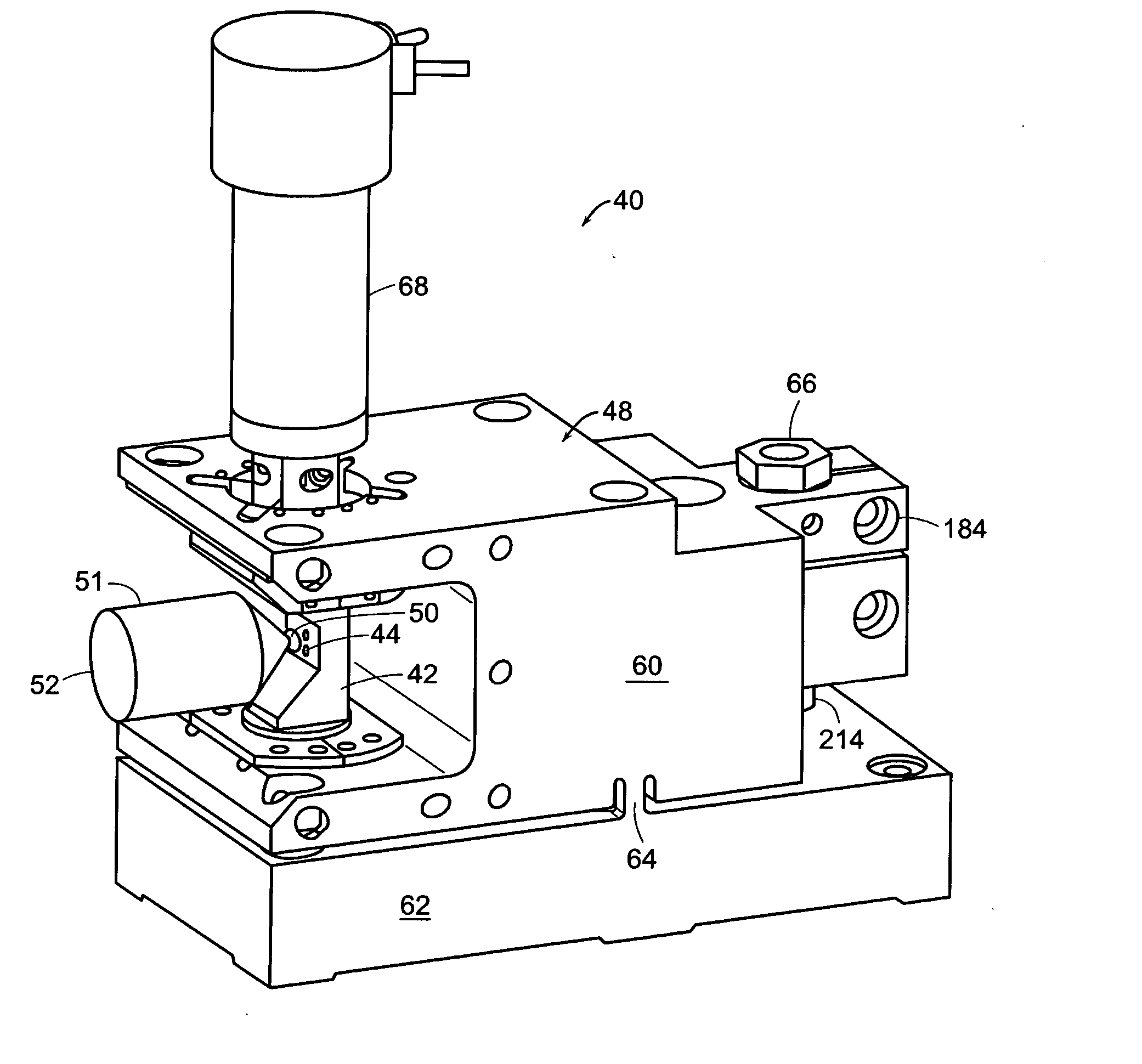
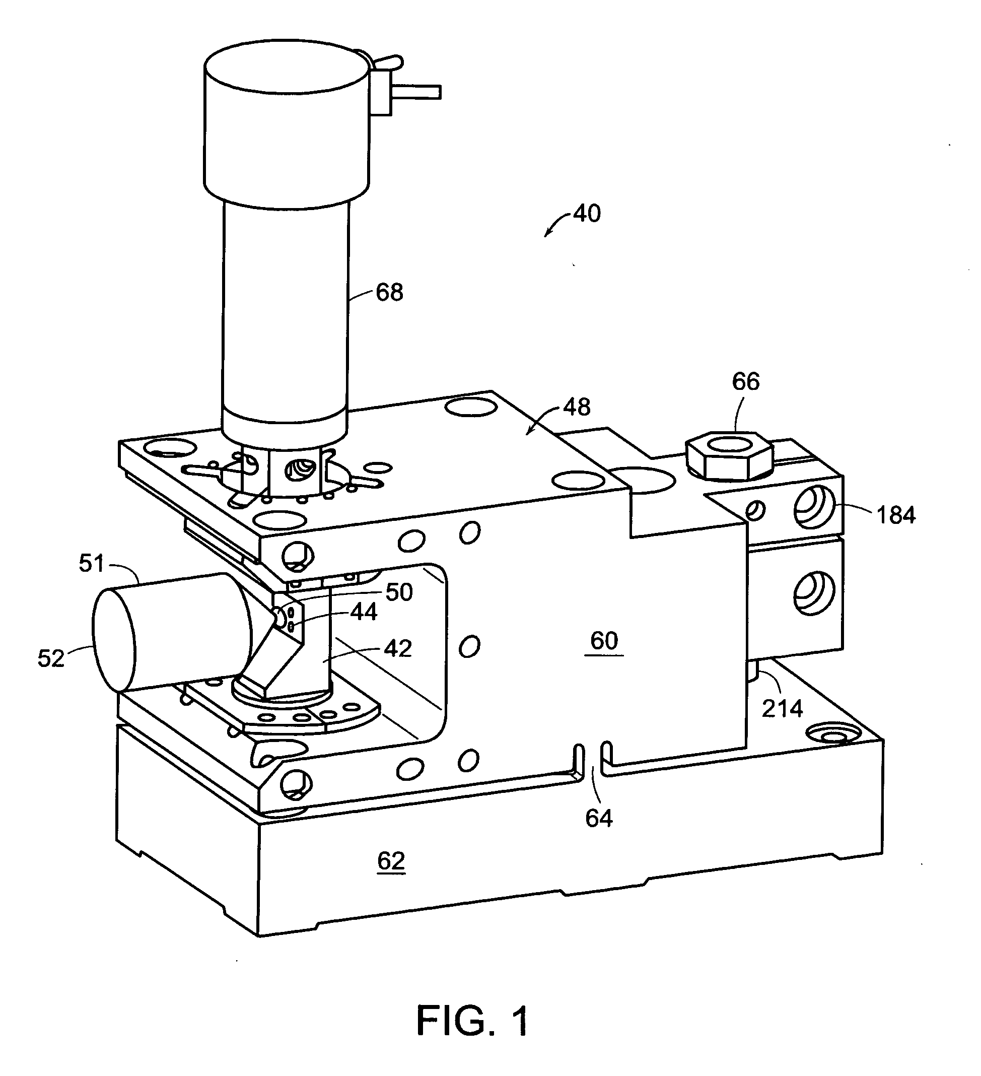
[0097] Referring to the drawings in detail, a high bandwidth rotary fast tool servo system is illustrated in accordance with a preferred embodiment of the present invention designated generally as 40. In a preferred embodiment, the high bandwidth rotary fast tool servo provides tool motion in a direction nominally parallel to the surface-normal of a workpiece at the point of contact between the cutting tool and workpiece.

[0098]FIG. 1 shows the high bandwidth rotary fast tool servo 40 having a swing arm assembly 42 holding a cutting tool 44 to machine a workpiece 50. The cutting tool 44 is offset from the axis of rotation 46, as best seen in FIG. 5, of the swing arm assembly 42. The workpiece 50 is held typically by a workpiece holder 51 that attaches to a lathe spindle at surface 52. The swing arm assembly 42 is supported in a base 48 having an upper portion 60 and a lower portion 62. The upper portion 60 and lower portion 62 are connected by a flexure hinge 64. The upper portion 6...


PUM

PropertyMeasurementUnit
Frequencyaaaaaaaaaa
Frequencyaaaaaaaaaa
Speedaaaaaaaaaa

Abstract

A high bandwidth rotary fast tool servo provides tool motion in a direction nominally parallel to the surface-normal of a workpiece at the point of contact between the cutting tool and workpiece. Three or more flexure blades having all ends fixed are used to form an axis of rotation for a swing arm that carries a cutting tool at a set radius from the axis of rotation. An actuator rotates a swing arm assembly such that a cutting tool is moved in and away from the lathe-mounted, rotating workpiece in a rapid and controlled manner in order to machine the workpiece. One or more position sensors provides rotation and position information for a swing arm to a control system. A control system commands and coordinates motion of the fast tool servo with the motion of a spindle, rotating table, cross-feed slide, and in-feed slide of a precision lathe.

Description

CROSS REFERENCES TO RELATED APPLICATIONS [0001] The present application is a continuation-in-part of co-pending U.S. patent application Ser. No. 10 / 448,336, filed May 29, 2003 and claims the benefit of U.S. Provisional Application No. 60 / 383,956, filed on May 29, 2002. The entire contents of the above applications are incorporated herein by reference.GOVERNMENT SUPPORT [0002] This invention was supported, in whole or in part, by Lawrence Livermore National Laboratory grant number 6892117. The Government has certain rights in the invention.BACKGROUND OF THE INVENTION [0003] A fast tool servo is a well-known device that can be added to a new or existing machine tool to provide an additional axis of motion between the cutting tool and a workpiece. A fast tool servo most notably distinguishes itself by its ability to move the tool at a much higher bandwidth, that is at a high speed of controlled, repetitive motion, on its axis relative to the other machine tool axes, with accuracy equal...

Claims


Application Information

Patent Timeline
IPC IPC(8): B23B5/00B23B29/04B23Q1/36B23Q1/52B23Q1/70B23Q5/22B23Q5/28B24B13/04
CPCB23B5/00B23B29/04B23Q1/36B23Q1/52B23Q1/70Y10T82/2583B23Q5/28B24B13/046B23Q2210/002Y10T82/10Y10T82/2585B23Q5/22
Inventor MONTESANTI, RICHARD C.TRUMPER, DAVID L.
Owner MASSACHUSETTS INST OF TECH
Why Eureka
Try Eureka