[0008] One object of the invention is to provide, in a simple and inexpensive manner, a chipper knife which allows cutting of chips of a more
uniform size, and in particular of a more uniform thickness, than is possible using conventional chipper knives according to prior art, while reducing especially the amount of oversized chips. Another object is to allow operation of a chipper, equipped with such chipper knives, at a low
power consumption and with little wear. At least these objects are achieved by means of a chipper knife according to claim 1.
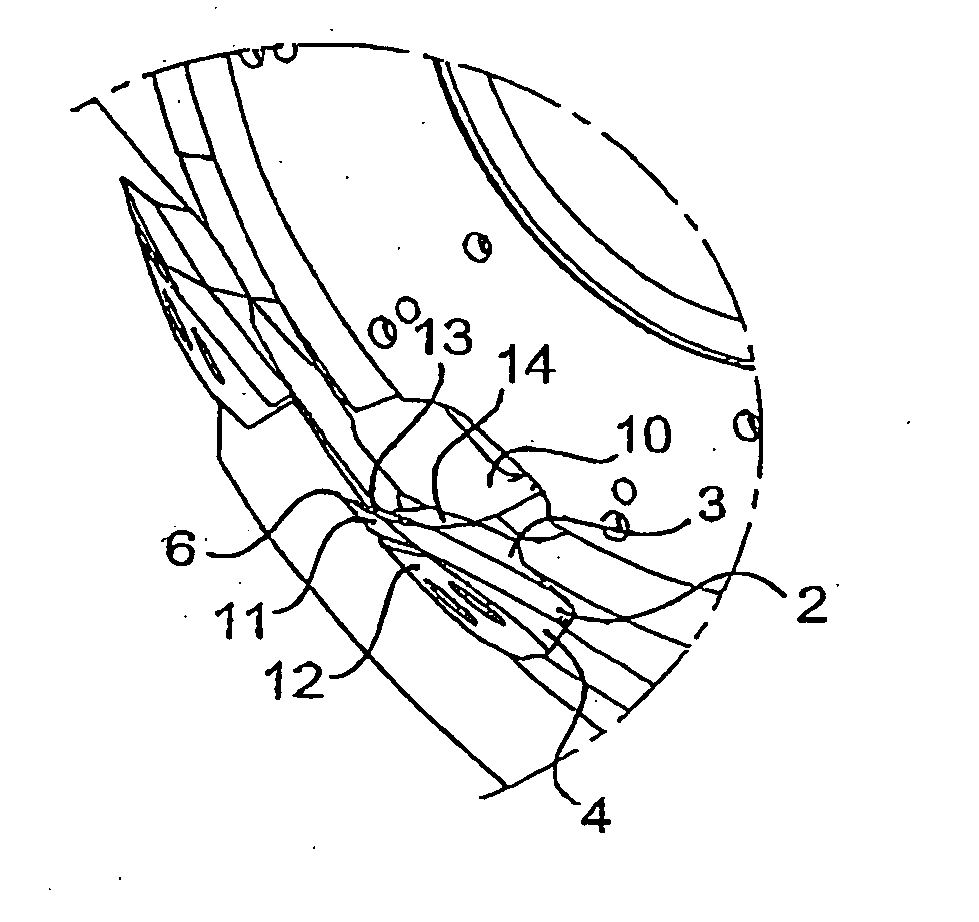
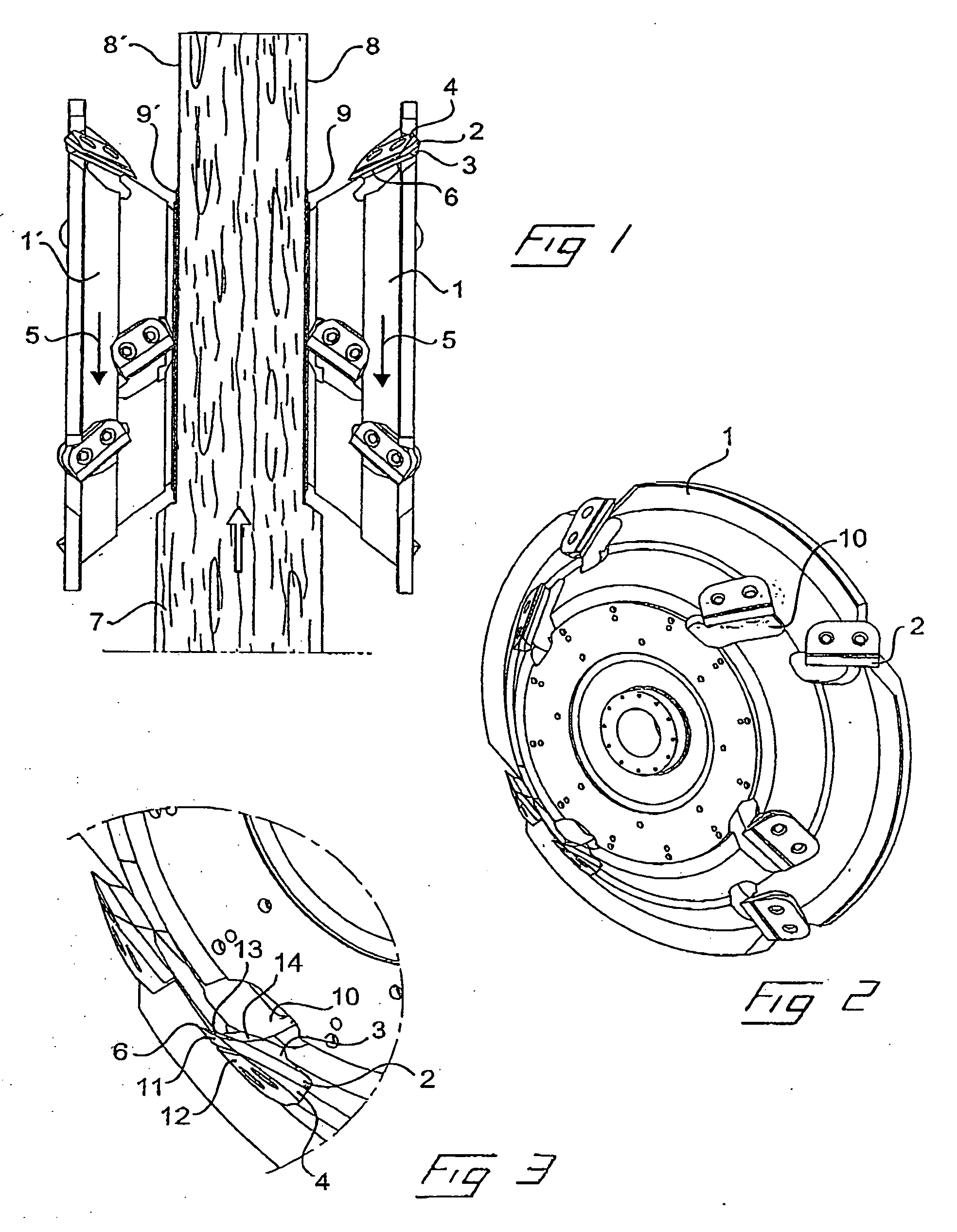
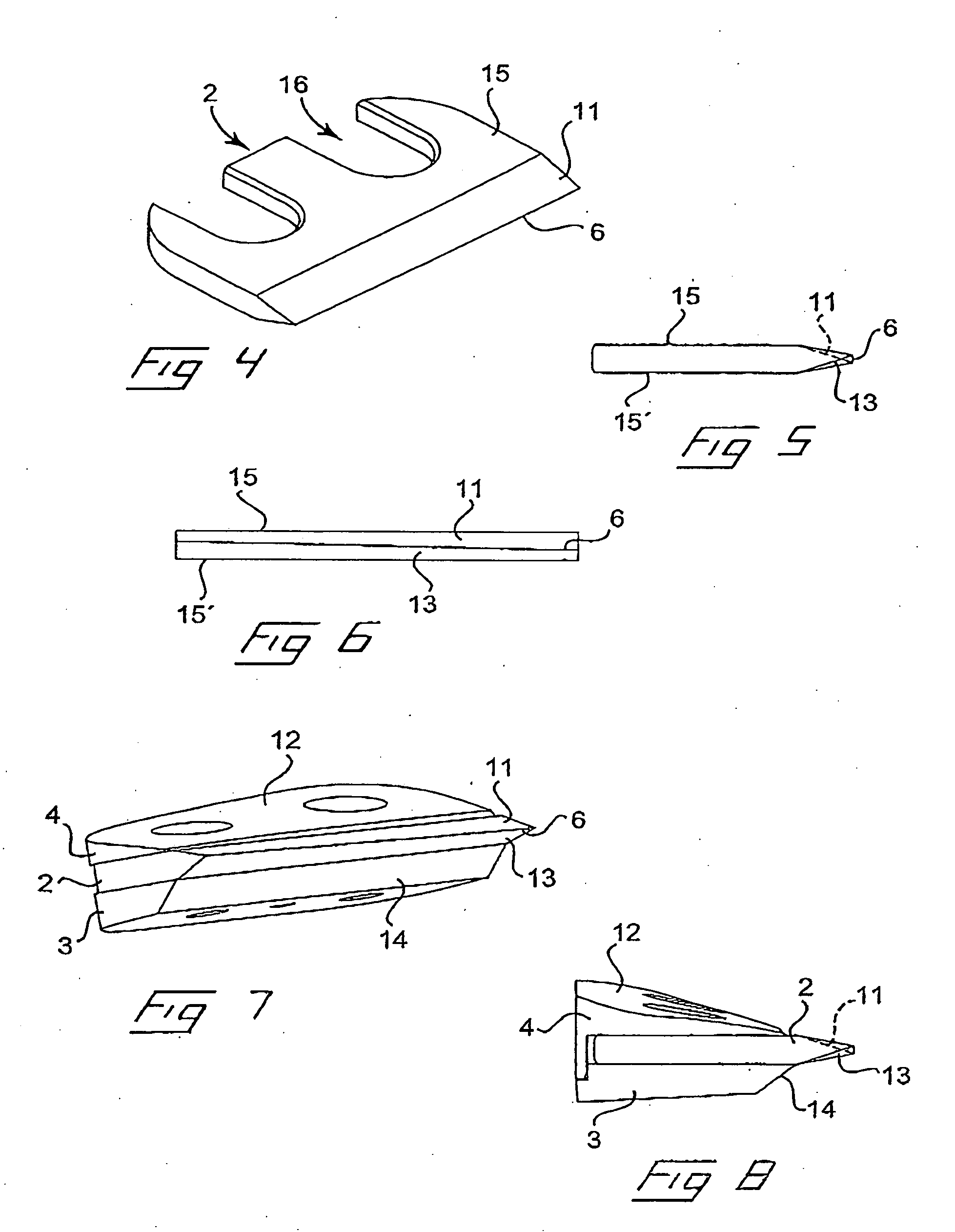
[0010] The invention is thus based on the understanding that the chip quality, i.e. the uniform shape of the chips, such as the uniform length of the chips and, in particular, the uniform thickness of the chips with a reduction of the amount of oversized chips, can be considerably improved by providing a chipper knife having a twisted edge-forming timber-guiding surface with a cutting edge whose edge angle is constant, i.e. with a correspondingly twisted chip-guiding surface.
[0014] It has been found that in chipper knives according to U.S. Pat. No. 2,183,224, in which the timber-guiding surface of the chipper knife has a twisted shape, while the chip-guiding surface is plane making a
constant angle to the direction of rotation along the whole length of the chipper knife, the part of the cutting edge of the chipper knife that is located closest to the axis of rotation, and that has a smaller cutting edge angle, will cut chips of a smaller average thickness than the part of the chipper knife that is located furthest away from the axis of rotation and that, thus, has a larger cutting edge angle. Since the cutting edge of the chipper knife, according to the invention, will have a constant and advantageously small cutting edge angle along its whole length, and thus also a greater residual angle in mounted state during operation in the chipper, the amount of oversized chips will be reduced and less force will be required to operate the
machine leading to reduced
power consumption and wear. When selling chips for pulp production the maximum price is obtained for so called acceptable chips, the size of which is within a predetermined size range. All chips of sizes falling outside of this range are screened out or sold at a lower price. The percentage of acceptable chips from a chipper is usually in the range of about 70-80% A one percent increase the share of acceptable chips can mean a considerable increase in revenue for a sawmill or a producer of pulp.
[0015] According to a preferred embodiment of the invention, the chipper knife has an essentially flat shape and both the timber-guiding surface and the chip-guiding surface, which form the cutting edge of the chipper knife, are obtained by means of bevel
grinding relative to respectively the outer and the inner main surface of the chipper knife. This allows both the timber-guiding surface and the chip-guiding surface, which both have a twisted shape that is relatively complicated from the point of manufacture, to be made with a small cross-sectional extension, which minimizes the amount of complex
machining required. However, it will be appreciated that the invention is applicable also in the case of chipper knives, in which one of the timber-guiding or chip-guiding surface is formed by one of the main surfaces of the chipper knife. This implies, however, a considerable increase in the amount of
machining required. It will further be appreciated that the invention is applicable to other types of chipper knives than those of an essentially plane shape, such as a chipper knife of the kind shown in Applicant's WO 02 / 06022. Moreover, in the preferred embodiment, both the timber-guiding surface and the chip-guiding surface have a cross-sectionally rectilinear extension. However, it would be perfectly possible to make, for example, the timber-guiding surface with an arched cross-sectional shape for conical chippers to allow the timber-guiding surface to better follow the ideal
cam curve between two chipper knives.
[0018] According to a particularly preferred embodiment, the chipper knife is symmetrical about a plane perpendicular to the chipper knife and through its centre. Such a design affords the additional
advantage of allowing the chipper knife to be turned end-for-end, i.e. when the inner end of the cutting edge of the chipper knife, which end is located closest to the axis of rotation and subjected, during cutting, to the greatest wear, is worn to such a degree that its cutting properties have been considerably reduced, the chipper knife can be turned end-for-end in such manner that the end that was previously facing outwards and located furthest away from the axis of rotation is disposed closest to the axis of rotation. This allows optimal exploitation of the operational life of the chipper knife. It would also be possible to apply the invention to a chipper knife having two opposite, twisted cutting edges, i.e. to make the chipper knife symmetrical also about a
plane parallel to its longitudinal extension and through its centre. This allows the chipper knife to be turned so that the previously inactive cutting edge is positioned for cutting chips. The chipper knifes can be either resharpenable or directly replaceable when worn.


