
Labels and method of manufacture thereof

Inactive Publication Date: 2005-08-04
FIELD GROUP
View PDF5 Cites 15 Cited by
  • Summary
  • Abstract
  • Description
  • Claims
  • Application Information

AI Technical Summary

Benefits of technology

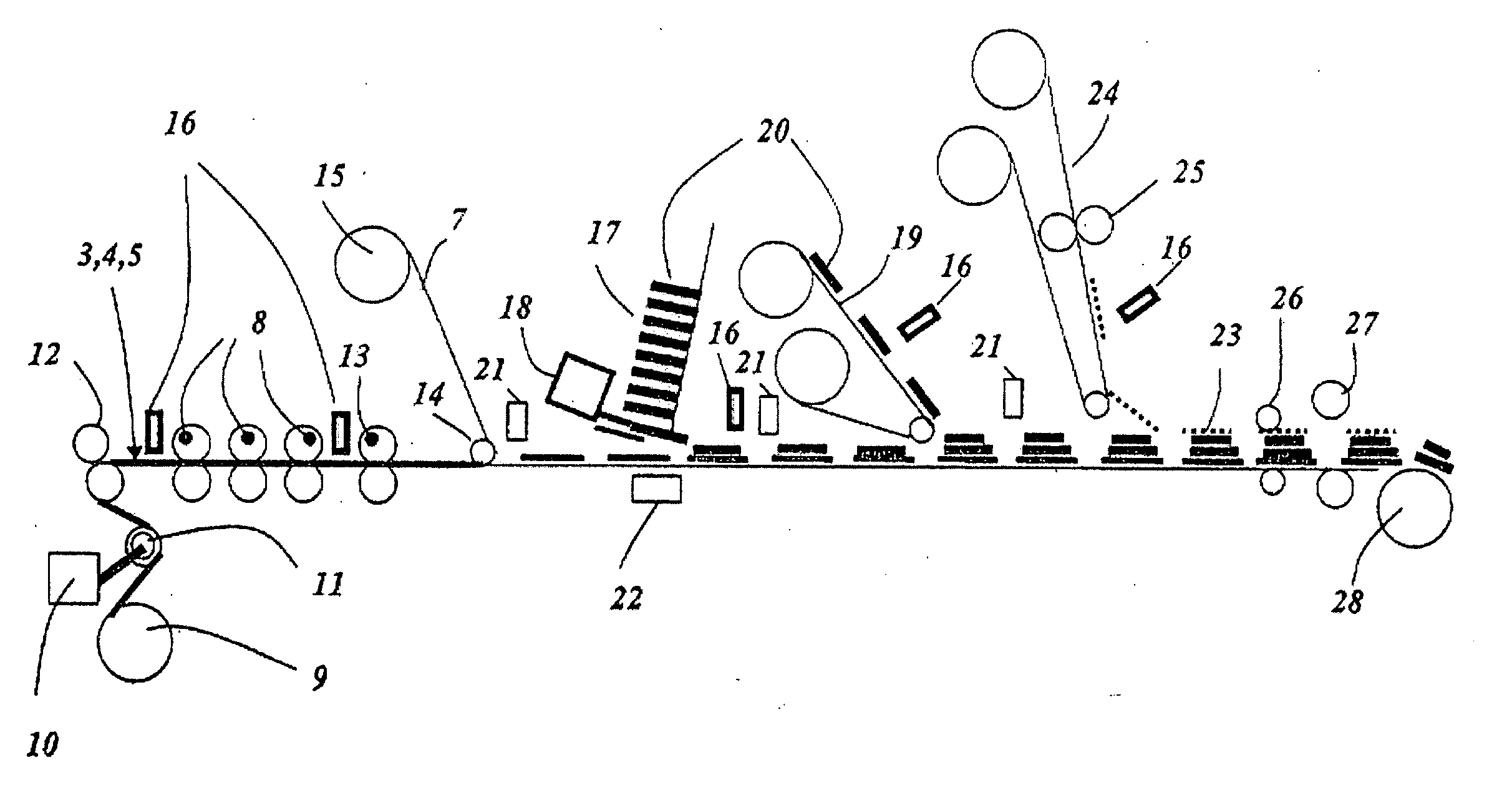
[0019] The use of two or more over-laminating dispensers in a single stream enables two or more over-laminates to be affixed to one base carrier label product. This may further enhance the product, allowing security information, for example, to be covered or disguised, and / or allows different regions of the base carrier label to have different and / or multiple over-labels.
[0020] By providing a multi-layer label comprising a number of label components, it is possible to provide a composite label fulfilling a number of functions. For example, the resultant label may include both a product information leaflet and an overt or covert security device. In this way, the need to apply two separate items to the product is avoided, reducing handling costs and requiring less space on the product itself. This makes the security tagging of small but expensive products a much more realistic option, where previously, space restrictions prevented the use of such devices.
[0021] By providing a separate component applicator for each label component to be applied, variable end-label effects can be achieved in a single process run. By careful selection of the component applicators and label components, it is possible to apply a different label components to each stream across the width of the web, so that a variety of end-label types can be produced simultaneously. This allows, SUBSTITUTE for example, the geometric shape, image and / or information to be varied across the web.
[0022] The method also allows different combinations of different pre-shaped components, including an over-laminate label, to be placed on different shaped and pitched carrier labels simultaneously, but then for each stream to be individually slit from its neighbouring one for individual subsequent processing. This facilitates differing and varying marketing information and designs to be affixed to carrier labels in the same in-line production run, and even the supply of alternate leaflets to sequential carrier labels or double leaflets to a single carrier label.
[0023] In a similar way, the dispensing of the label components by use of two or more applicators may achieve additional variations of end product for each base carrier label stream sequence. Using this system, label components may be introduced “randomly”. This facility has benefits in market areas such as toys, security and special promotional work where “special” over-laminate labels can be applied to produce “winning numbers” or special security effects and codes within a sequence of products.
[0025] The provision of a registration system between each label component applicator and its respective carrier label ensures that each label component is dispensed in a phased and controlled way. The adoption of a single continuous in line operation has the further advantage of significant production costs and register benefits, because of the ability to register all the base carrier labels and each label component far more accurately to each other than is possible if they are produced and applied in a non continuous in-line way.

Problems solved by technology

Where the size of the product is limited, such as on camera film containers, computer consumables etc, the “footprint” of the leaflet must be kept to a minimum, which can result in increased leaflet bulk.
Bulky labels can be difficult to produce with conventional manufacturing methods, and difficult to apply to the products.
Whilst such methods have the advantage of producing high volumes of labels quickly and cost-effectively, the methods are unsuitable for less conventional label types.

Method used


Image

  • Labels and method of manufacture thereof
  • Labels and method of manufacture thereof
  • Labels and method of manufacture thereof

Examples


Embodiment Construction

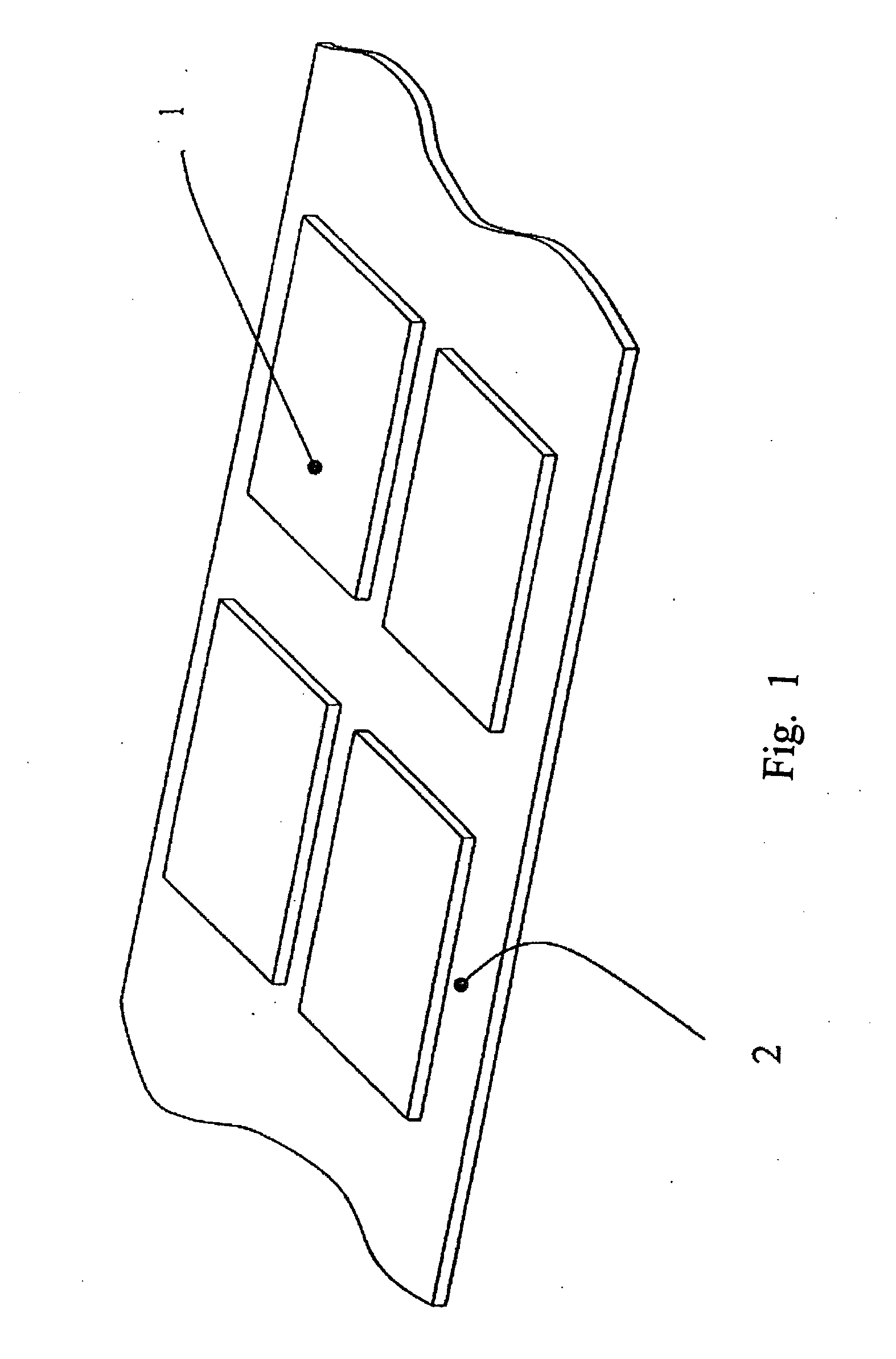
[0049]FIG. 1 shows a base carrier label, which has been formed on a continuous carrier substrate 2 and held in place using a suitable pressure sensitive adhesive. Multiple labels are provided across the width of the carrier substrate 2 (with two labels being illustrated in FIG. 1) with the configuration being repeated down the length of the carrier substrate 2. The top surface of the carrier substrate 2 may be coated, for example with a silicone material, to form a release sheet from which the carrier labels 1 can be easily removed.

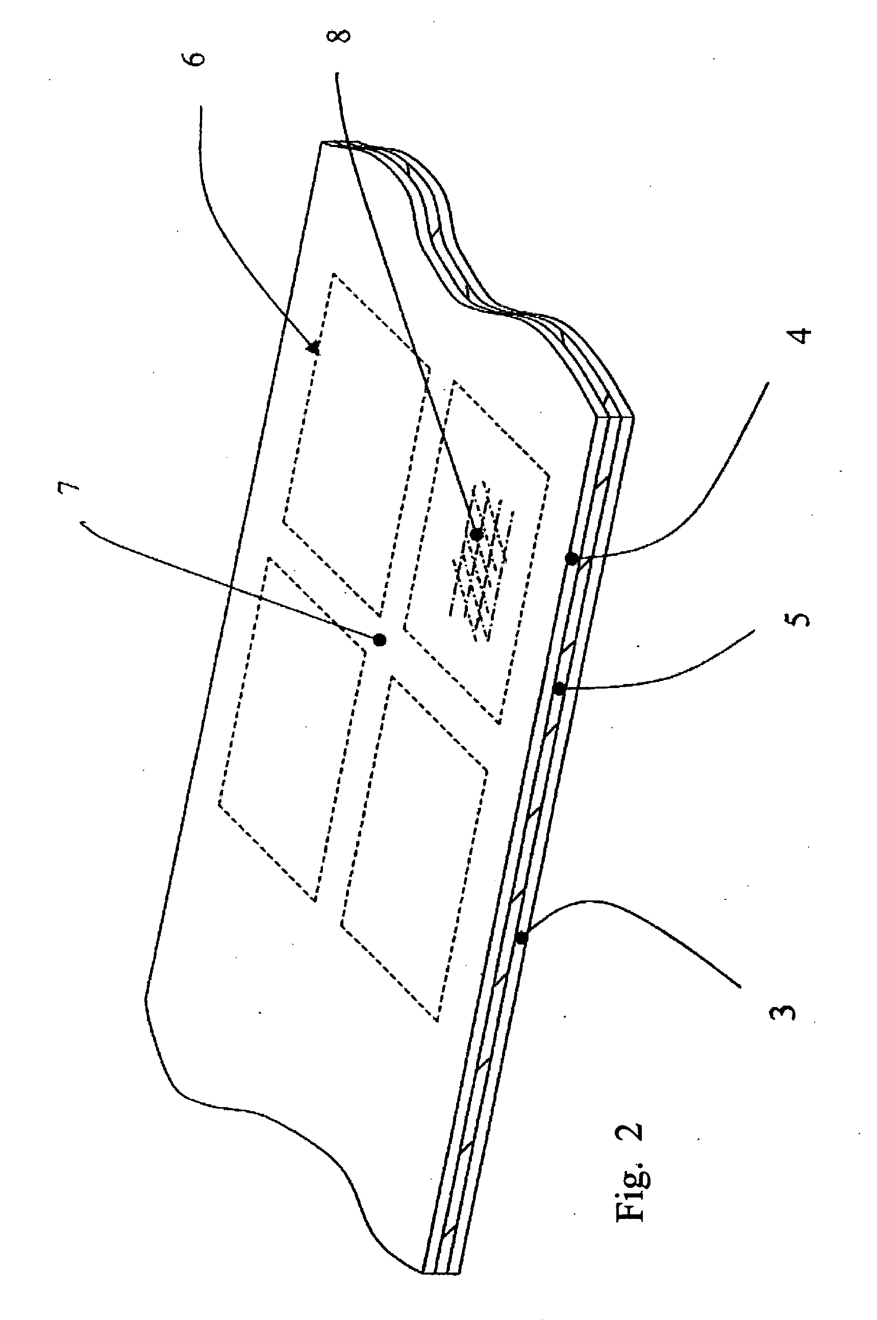
[0050] The carrier labels 1 may have previously been formed by cutting the shape of the labels from the upper layer of a typical multi-layer pressure sensitive label substrate stock such as shown in FIG. 2. The stock would normally comprise a paper carrier layer 3 with an appropriate silicone or wax release surface, a plastic (typically Polyethylene {PE}, Polypropylene {PP}, Polyester {PET}, Polyvinyl chloride {PVC}) or paper upper layer 4 and pressure s...


PUM

PropertyMeasurementUnit
Lengthaaaaaaaaaa
Adhesivityaaaaaaaaaa
Widthaaaaaaaaaa

Abstract

A method of producing self-adhesive labels carried on a release backing material is described. This method provides a plurality of self-adhesive carrier labels across the width of a web of carrier substrate with at least one discrete label components, such as a leaflets, booklets, holograms and security devices, being applied to each respective carrier label. The invention provides a plurality of separate label component applicators across the width of the web, one for each respective label component to be applied. There is also provided a registration means to ensure registration of each label component with its respective carrier label. In this way the method provides for the manufacture of multi-layered combinations of individual labels to a base carrier using separate and specific component applicators for each label across the width of the web.

Description

CROSS-REFERENCE TO RELATED APPLICATIONS [0001] This application is entitled to the benefit of and incorporates by reference essential subject matter disclosed in International Patent Application No. PCT / GB2004 / 001661 filed on Apr. 16, 2004 and British Patent Application No. 0308934.9 filed on Apr. 17, 2003.FIELD OF THE INVENTION [0002] The present invention relates to a label and a method of manufacturing labels. In particular, the invention relates to a method of manufacturing a multi-laminar label, comprising a self-adhesive base label which serves as a carrier for additional layers comprising, for example leaflets or booklets including information relevant to the product to which the label is to be applied. BACKGROUND OF THE INVENTION [0003] In the current market conditions, there is a growing requirement to provide consumers with increased product information. This need can stem from legal requirements (for example for pharmaceutical products or agro-chemical products), and for ...

Claims


Application Information

Patent Timeline
IPC IPC(8): B31D1/02
CPCB31D1/021Y10T156/1097G06K19/0776G06K19/07718B31D1/02G09F3/02G09F3/0286
Inventor EXETER, MALCOLM KEITHATKINS, PAUL GEOFFREYTHOMPSON, IAN
Owner FIELD GROUP
Learn More