Dry etching apparatus and dry etching method

a technology of dry etching and dry etching, which is applied in the direction of electrical apparatus, electrical discharge tubes, basic electric elements, etc., can solve the problems of deteriorating the uniformity of the etching rate of the whole to-be-processed substrate, high difficulty level of high-selectivity etching of siosub>x /sub>film using sin as an etching stopper film, and inconvenience of the etching apparatus, so as to improv

Active Publication Date: 2005-08-04
PANNOVA SEMIC
View PDF1 Cites 9 Cited by
  • Summary
  • Abstract
  • Description
  • Claims
  • Application Information

AI Technical Summary

Benefits of technology

[0020] An object of the present invention is to improve the uniformity of etching shape in a substrate surface region even under the use of an etching apparatus having a small electrode-to-electrode distance to obtain a desired etching shape. More specifically, an object of the present invention is to prevent, in the formation of contact holes on a large diameter to-be-processed substrate using an etching apparatus having a small electrode-to-electrode distance, a contact hole on the middle part of the to-be-processed substrate from having a tapered shape to obtain contact holes of desired shape.

Problems solved by technology

In view of these points, the high-selectivity etching of a SiOx film using SiN as an etching stopper film is considered to have an extremely high difficulty level.
Since the etching rate is therefore decreased in the peripheral part of the to-be-processed substrate, this deteriorates the uniformity of the etching rate of the whole to-be-processed substrate.
However, the use of such an etching apparatus causes an inconvenience as described hereinafter. FIGS. 12A through 12C are cross-sectional views for explaining a problem on the formation of a contact hole in a large-diameter to-be-processed substrate under the use of an etching apparatus having a small electrode-to-electrode distance.
This deteriorates the uniformity of the hole diameters in the surface region of the to-be-processed substrate.

Method used


Image

  • Dry etching apparatus and dry etching method
  • Dry etching apparatus and dry etching method
  • Dry etching apparatus and dry etching method

Examples


embodiment 1

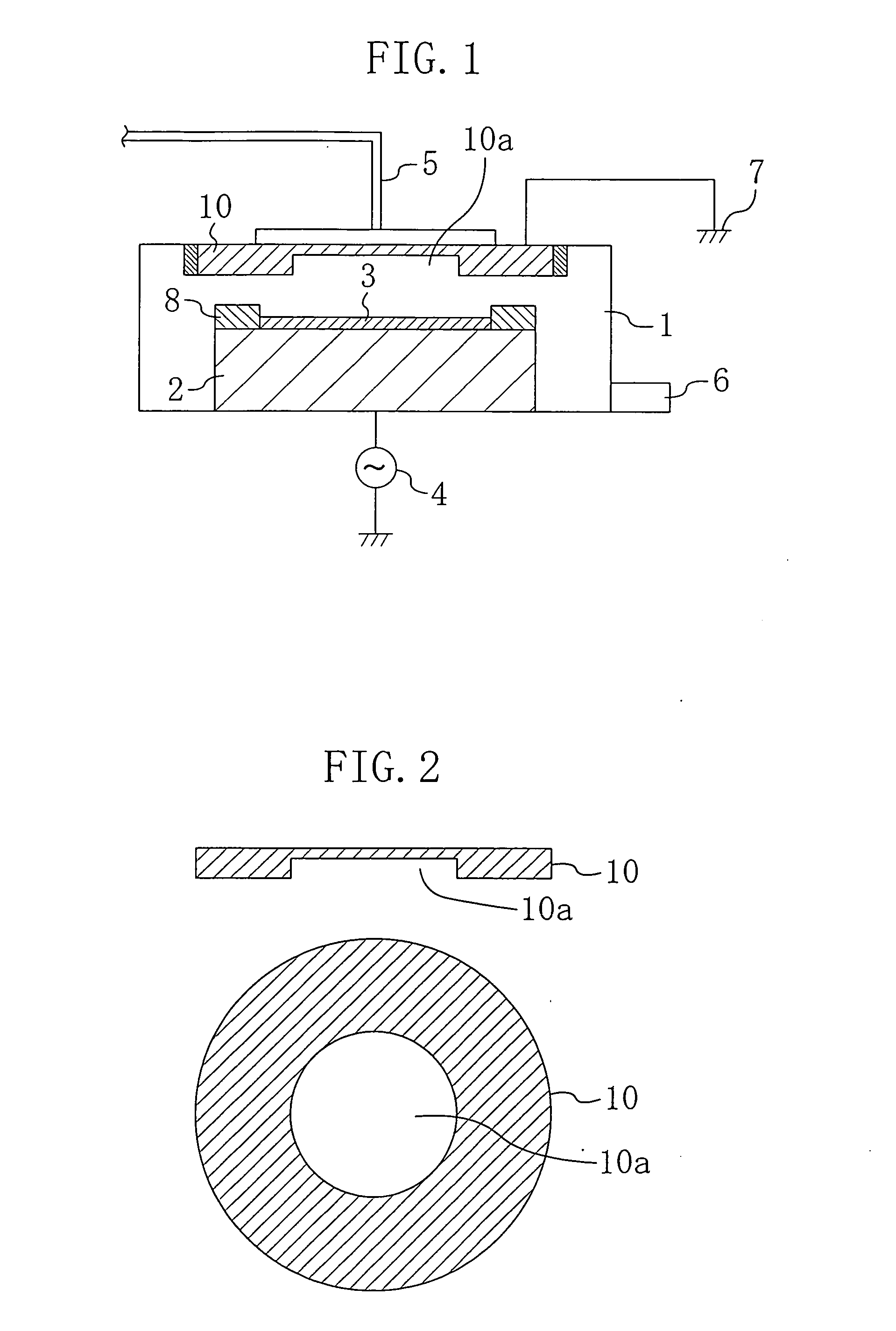
[0052] A dry etching apparatus and method according to a first embodiment of the present invention will be described hereinafter with reference to the drawings. Etching for forming a contact hole in an oxide film will now be given as an example. FIG. 1 is a schematic view showing the structure of a dry etching apparatus according to the first embodiment.

[0053] As shown in FIG. 1, a lower electrode 2 is provided on the bottom of a reaction chamber 1, and an upper electrode 10 is provided at the ceiling of the reaction chamber 1 to face the lower electrode 2. The lower electrode 2 and upper electrode 10 are separated from each other by as large a space as necessary to generate plasma.

[0054] A focus ring 8 is placed on the lower electrode 2 to hold a to-be-processed substrate (wafer) 3. The focus ring 8 has, at its center, a cavity for holding the to-be-processed substrate 3.

[0055] An RF power supply 4 is provided outside of the reaction chamber 1 to apply voltage to the lower elect...

embodiment 2

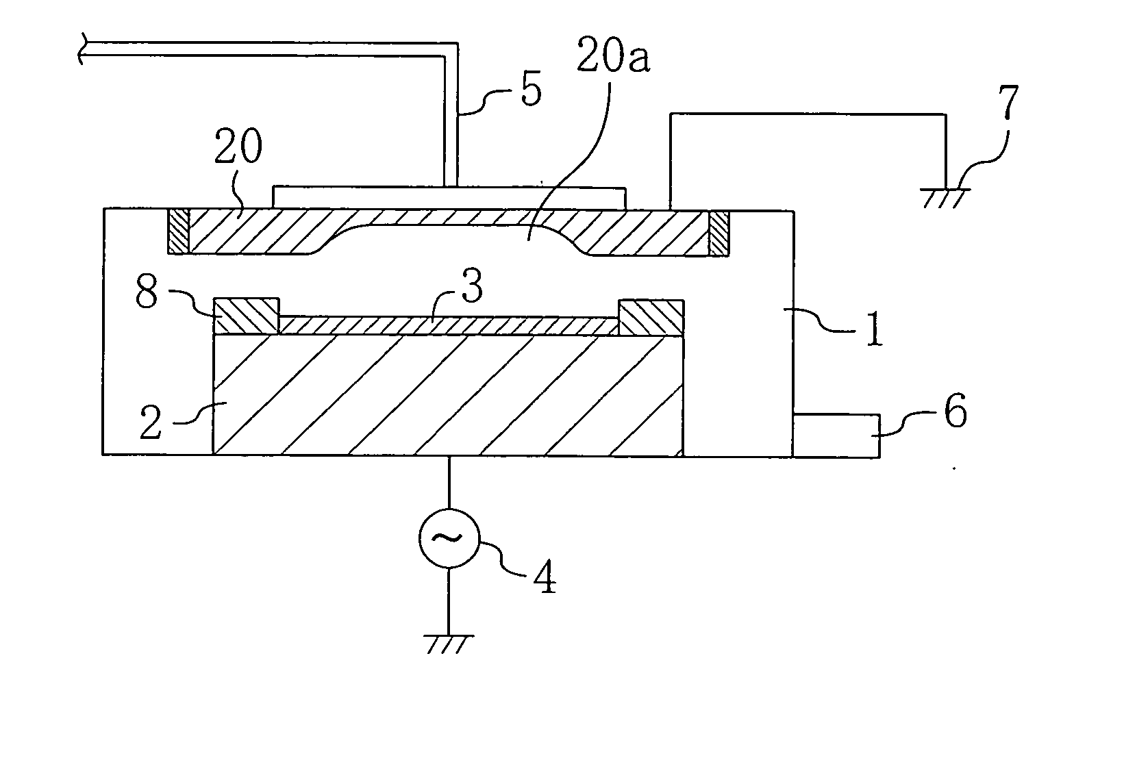
[0067] A dry etching apparatus and method according to a second embodiment of the present invention will be described hereinafter with reference to the drawings. Etching for forming contact holes in an oxide film will be described below as an example. FIG. 4 is a schematic view showing the structure of a dry etching apparatus according to the second embodiment. In FIG. 4, the same reference numerals are given to the same members as those of the dry etching apparatus shown in FIG. 1 of the first embodiment.

[0068] The second embodiment is different from the first embodiment in the structure of an upper electrode 20. To be specific, a dome-shaped recess 20a with an inside diameter of 15 cm is formed in the middle part of the upper electrode 20 having an outside diameter of 20 cm and a thickness of 20 mm. The dome-shaped recess 20a has a maximum depth of 5 mm in its middle part, i.e., in the middle part of the upper electrode 20 and becomes shallower with the increase in distance from ...

embodiment 3

[0079] A dry etching apparatus and method according to a third embodiment of the present invention will be described hereinafter with reference to the drawings. Etching for forming a contact hole in an oxide film will be described below as an example. FIG. 6 is a schematic view showing the structure of a dry etching apparatus according to the third embodiment. In FIG. 6, the same reference numerals are given to the same members as those of the dry etching apparatus shown in FIG. 1 of the first embodiment. A description is not given of the members herein.

[0080] The third embodiment is different from the first embodiment in the structure of an upper electrode 30. The upper electrode 30 is composed of two electrodes: a middle part 32 having a thickness of 20 mm and an outside diameter of 10 cm and a doughnut-shaped peripheral part 31 surrounding the side surface of the middle part 32 and having a thickness of 20 mm and an outside diameter of 20 cm. The distance between each of the mid...


PUM

PropertyMeasurementUnit
hole diameteraaaaaaaaaa

Abstract

An etching apparatus of the present invention comprises a reaction chamber, a lower electrode placed on the bottom surface of the reaction chamber, an upper electrode placed at the ceiling of the reaction chamber to face the lower electrode, and a focus ring placed on the lower electrode and having a cavity for holding a to-be-processed substrate. The lower surface of the upper electrode is provided, at its middle part, with a recess having a smaller inside diameter than the diameter of the to-be-processed substrate. Thus, in the generation of plasma, the amount of further incident radicals can be reduced in a middle part of the to-be-processed substrate. Therefore, a hole or the like located in the middle part of the to-be-processed substrate can be formed to have a desired shape without having a tapered shape.

Description

CROSS-REFERENCE TO RELATED APPLICATIONS [0001] This application claims priority under 35 U.S.C. §119 on Patent Application No. 2004-22825 filed in Japan on Jan. 30, 2004, the entire contents of which are hereby incorporated by reference. BACKGROUND OF THE INVENTION [0002] (1) Field of the Invention [0003] The present invention relates to a dry etching apparatus and a dry etching method. [0004] (2) Description of Related Art [0005]FIG. 10 schematically shows the structure of a known dry etching apparatus for use in etching of oxide films or other films. [0006] As shown in FIG. 10, a lower electrode 102 is provided on the bottom of a reaction chamber 101, and an upper electrode 110 is provided at the ceiling of the reaction chamber 101 to face the lower electrode 102. The lower electrode 102 and upper electrode 110 are separated from each other by as large a space as necessary to generate plasma. A focus ring 108 is placed on the lower electrode 102 to hold a to-be-processed substrate...

Claims


Application Information

Patent Timeline
Patent Type & Authority Applications(United States)
IPC IPC(8): H01L21/00H01L21/311H01L21/768H01L21/3065
CPCH01J37/32082H01J37/32568H01L21/76802H01L21/67069H01L21/31116
Inventor OIKAWA, KOTA
Owner PANNOVA SEMIC
Why Eureka
Try Eureka